Quantcast
Channel: Ken Shirriff's blog
Viewing all 317 articles
Browse latest View live

Understanding silicon circuits: inside the ubiquitous 741 op amp

$
0
0
The 741 op amp is one of the most famous and popular ICs[1] with hundreds of millions sold since its invention in 1968 by famous IC designer Dave Fullagar. In this article, I look at the silicon die for the 741, discuss how it works, and explain how circuits are built from silicon.

The 741 op amp, packaged in a TO-99 metal can.

The 741 op amp, packaged in a TO-99 metal can.

I started with a 741 op amp that was packaged in a metal can (above). Cutting the top off with a hacksaw reveals the tiny silicon die (below), connected to the pins by fine wires.

Inside a 741 op amp, showing the die. This is a TO-99 metal can package, with the top sawed off

Inside a 741 op amp, showing the die. This is a TO-99 metal can package, with the top sawed off

Under a microscope, the details of the silicon chip are visible, as shown below. At first, the chip looks like an incomprehensible maze, but this article will show how transistors, resistors and capacitors are formed on the chip, and explain how they combine to make the op amp.

Die photo of the 741 op amp

Die photo of the 741 op amp

Why op amps are important

Op amps are a key component in analog circuits. An op amp takes two input voltages, subtracts them, multiplies the difference by a huge value (100,000 or more), and outputs the result as a voltage. If you've studied analog circuits, op amps will be familiar to you, but otherwise this may seem like a bizarre and pointless device. How often do you need to subtract two voltages? And why amplify by such a huge factor: will a 1 volt input result in lightning shooting from the op amp? The answer is feedback: by using a feedback signal, the output becomes a sensible value and the high amplification makes the circuit performance stable.

Op amps are used as amplifiers, filters, integrators, differentiators, and many other circuits.[2] Op amps are all around you: your computer's power supply uses op amps for regulation. Your cell phone uses op amps for filtering and amplifying audio signals, camera signals, and the broadcast cell signal.

The structure of the integrated circuit

NPN transistors inside the IC

Transistors are the key components in a chip. If you've studied electronics, you've probably seen a diagram of a NPN transistor like the one below, showing the collector (C), base (B), and emitter (E) of the transistor, The transistor is illustrated as a sandwich of P silicon in between two symmetric layers of N silicon; the N-P-N layers make a NPN transistor. It turns out that transistors on a chip look nothing like this, and the base often isn't even in the middle!

Symbol and oversimplified structure of an NPN transistor.

Symbol and oversimplified structure of an NPN transistor.

The photo below shows one of the transistors in the 741 as it appears on the chip. The different brown and purple colors are regions of silicon that has been doped differently, forming N and P regions. The whitish-yellow areas are the metal layer of the chip on top of the silicon - these form the wires connecting to the collector, emitter, and base.

Underneath the photo is a cross-section drawing showing approximately how the transistor is constructed. There's a lot more than just the N-P-N sandwich you see in books, but if you look carefully at the vertical cross section below the 'E', you can find the N-P-N that forms the transistor. The emitter (E) wire is connected to N+ silicon. Below that is a P layer connected to the base contact (B). And below that is a N+ layer connected (indirectly) to the collector (C).[3] The transistor is surrounded by a P+ ring that isolates it from neighboring components.

Structure of a NPN transistor in the 741 op amp

Structure of a NPN transistor in the 741 op amp

PNP transistors inside the IC

You might expect PNP transistors to be similar to NPN transistors, just swapping the roles of N and P silicon. But for a variety of reasons, PNP transistors have an entirely different construction. They consist of a circular emitter (P), surrounded by a ring shaped base (N), which is surrounded by the collector (P).[4] This forms a P-N-P sandwich horizontally (laterally), unlike the vertical structure of the NPN transistors.

The diagram below shows one of the PNP transistors in the 741, along with a cross-section showing the silicon structure. Note that although the metal contact for the base is on the edge of the transistor, it is electrically connected through the N and N+ regions to its active ring in between the collector and emitter.

Structure of a PNP transistor in the 741 op amp.

Structure of a PNP transistor in the 741 op amp.

The output transistors in the 741 are larger than the other transistors and have a different structure in order to produce the high-current output. The output transistors must support 25mA, compared to microamps for the internal transistors. The photo below shows one of the output transistors. Note the multiple interlocking "fingers" of the emitter and base, surrounded by the large collector.

A high-current PNP transistor inside the 741 op amp

A high-current PNP transistor inside the 741 op amp

How resistors are implemented in silicon

Resistors are a key component of analog chips. Unfortunately, resistors in ICs are very inaccurate; the resistances can vary by 50% from chip to chip. Thus, analog ICs are designed so only the ratio of resistors matters, not the absolute values, since the ratios remain nearly constant from chip to chip.

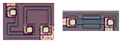
The photo below shows two resistors in the 741 op amp, formed using different techniques. The resistor on the left is formed from a meandering strip of P silicon, and is about 5KΩ. The resistor on the right is a pinch resistor and is about 50KΩ. In the pinch resistor, a layer of N silicon on top makes the conductive region much thinner (i.e. pinches it). This allows a much higher resistance for a given size. Both resistors are at the same scale below, but the pinch resistor has ten times the resistance. The tradeoff is the pinch resistor is much less accurate.

Two resistors from the 741 op amp. The left resistor is a simple 'base resistor', while the right resistor is a 'pinch resistor'.

Two resistors from the 741 op amp. The left resistor is a simple 'base resistor', while the right resistor is a 'pinch resistor'.

How capacitors are implemented in silicon

The 741's capacitor is essentially a large metal plate separated from the silicon by an insulating layer. The main drawback of capacitors on ICs is they are physically very large. The 25pF capacitor in the 741 has a very small value but takes up a large fraction of the chip's area.[5][6] You can see the capacitor in the middle of the die photo; it is the largest structure on the chip.

IC component: The current mirror

There are some subcircuits that are very common in analog ICs, but may seem mysterious at first. Before explaining the 741's circuit, I'll first give a brief overview of the current mirror and differential pair circuits.

Schematic symbols for a current source.

Schematic symbols for a current source.

If you've looked at analog IC block diagrams, you may have seen the above symbols for a current source and wondered what a current source is and why you'd use one. The idea of a current source is you start with one known current and then you can "clone" multiple copies of the current with a simple transistor circuit.

The following circuit shows how a current mirror is implemented.[7] A reference current passes through the transistor on the left. (In this case, the current is set by the resistor.) Since both transistors have the same emitter voltage and base voltage, they source the same current,[8] so the current on the right matches the reference current on the left.

Current mirror circuit. The current on the right copies the current on the left.

Current mirror circuit. The current on the right copies the current on the left.

A common use of a current mirror is to replace resistors. As explained earlier, resistors inside ICs are both inconveniently large and inaccurate. It saves space to use a current mirror instead of a resistor whenever possible. [9]

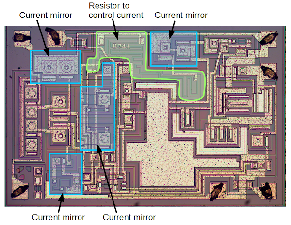
The diagram below shows that much of the 741 die is taken up by multiple current mirrors. The large resistor snaking around the upper middle of the IC controls the initial current. This current is then duplicated by multiple current mirrors, providing controlled currents to various parts of the chip. Using one large resistor and current mirrors is more compact and more accurate than using multiple large resistors. The current mirror in the middle is slightly different; it provides an active load for the input stage, improving the performance.

Die for the 741 op amp, showing the current mirrors, along with the resistor that controls the current.

Die for the 741 op amp, showing the current mirrors, along with the resistor that controls the current.

IC component: The differential pair

The second important circuit to understand is the differential pair, the most common two-transistor subcircuit used in analog ICs.[10] You may have wondered how the op amp subtracts two voltages; it's not obvious how to make a subtraction circuit. This is the job of the differential pair.

Schematic of a simple differential pair circuit. The current source sends a fixed current I through the differential pair. If the two inputs are equal, the current is split equally.

Schematic of a simple differential pair circuit. The current source sends a fixed current I through the differential pair. If the two inputs are equal, the current is split equally.

The schematic above shows a simple differential pair. The key is the current source at the top provides a fixed current I, which is split between the two input transistors. If the input voltages are equal, the current will be split equally into the two branches (I1 and I2). If one of the input voltages is a bit higher than the other, the corresponding transistor will conduct more current, so one branch gets more current and the other branch gets less. As one input continues to increase, more current gets pulled into that branch. Thus, the differential pair is a surprisingly simple circuit that routes current based on the difference in input voltages.

The internal blocks of the 741

The internal circuitry of the 741 op amp has been explained in many places[11], so I'll just give a brief description of the main blocks. The interactive chip viewer below provides more explanation.

The two input pins are connected to the differential amplifier, which is based on the differential pair described above. The output from the differential amplifier goes to the second (gain) stage, which provides additional amplification of the signal. Finally, the output stage has large transistors to generate the high-current output, which is fed to the output pin.

Die for the 741 op amp, showing the main functional units.

Die for the 741 op amp, showing the main functional units.
A key innovation that led to the 741 was Fairchild's development of a new process for building capacitors on ICs using silicon nitride.[12] Op amps before the 741 required an external capacitor to prevent oscillation, which was inconvenient.[13] Dave Fullagar had the idea to put the compensation capacitor on the 741 chip using the new manufacturing process. Doing away with the external capacitor made the 741 extremely popular, either because engineers are lazy[14] or because the reduced part count was beneficial.

Another feature that made the 741 popular is its short-circuit protection. Many integrated circuits will overheat and self-destruct if you accidentally short circuit an output. The 741, though, includes clever circuits to shut down the output before damage occurs.

Interactive chip viewer

The die photo and schematic below are interactive. Click components in the die photo or schematic[15] to explore the chip, and a description will be displayed below. NPN transistors are highlighted in blue and PNP transistors are in red.

How I photographed the 741 die

Integrated circuit usually come in a black epoxy package. Dangerous concentrated acid is required to dissolve the epoxy package and see the die. But some ICs, such as the 741, are available in metal cans which can be easily opened with a hacksaw.[16] I used this safer approach. With even a basic middle-school microscope, you can get a good view of the die at low magnification but for the die photos, I used a metallurgical microscope, which shines light from above through the lens. A normal microscope shines light from below, which works well for transparent cells but not so well for opaque ICs. A metallurgical microscope is the secret to getting clear photos at higher magnification, since the die is brightly illuminated.[17]

Conclusion

Despite being almost 50 years old, the 741 op amp illustrates a lot of interesting features of analog integrated circuits. Next time you're listening to music, talking on your cell phone, or even just using your computer, think about the tiny op amps that make it possible and the 741 that's behind it all.

See more comments on Hacker News, Reddit and Hackaday. Los comentarios en español en Menéame.

We've got a winner! 741 op amp marketing letter from 1968. Courtesy of Dave Fullagar.

We've got a winner! 741 op amp marketing letter from 1968. Courtesy of Dave Fullagar.

Thanks to Dave Fullagar for providing information on the 741, including the letter above, which shows that the 741 was an instant success.

Notes and references

[1] The 741 op amp is one 25 Microchips That Shook the World and is popular enough to be on mugs and multipletshirts, as well as available in a giant kit.

[2] To see the variety of circuits that can be built from an op amp, see this op amp circuit collection.

[3] You might have wondered why there is a distinction between the collector and emitter of a transistor, when the simple picture of a transistor is totally symmetrical. Both connect to an N layer, so why does it matter? As you can see from the die photo, the collector and emitter are very different in a real transistor. In addition to the very large size difference, the silicon doping is different. The result is a transistor will have poor gain if the collector and emitter are swapped.

[4] In many of the ICs that I've examined, it's easy to distinguish NPN and PNP transistors by their shape: NPN transistors are rectangular, while PNP transistors have circular emitters and bases with a circular metal layer on top. For some reason, this 741 chip uses rectangular and circular transistors for both NPN and PNP transistors. Thus, a closer examination is necessary to separate the NPN and PNP transistors.

[5] The capacitor in the 741 is located at a special point in the circuit where the effect of the capacitance is amplified due to something called the Miller effect. This allows the capacitor in the 741 to be much smaller than it would be otherwise. Given how much of the 741 die is used for the capacitor already, taking advantage of the Miller effect is very important.

[6] An alternative way to put capacitors on a chip is the junction capacitor, which is basically a large reverse-biased diode junction. The 741 doesn't use this technique; for more information on junction capacitors see my article on the TL431.

[7] For more information about current mirrors, you can check wikipedia, any analog IC book, or chapter 3 of Designing Analog Chips. If you're interested in how analog chips work, I strongly recommend you take a look at Designing Analog Chips.

[8] The current mirror doesn't provide exactly the same current for a variety of reasons. For instance, the base current is small but not zero. Transistor matching is very important: if the transistors are not identical, the currents will be different. (Using a single transistor with two collectors helps with matching.) If the collector voltages are different, the Early effect will cause the currents to be different. More complex current mirror circuits can reduce these problems.

[9] The 741 uses are several common extensions of the current source. First, by adding additional output transistors, you can create multiple copies of the current. Second, if you use a transistor with twice the collector size, you will get an output with twice the current (for instance). Third, instead of multiple output transistors, you can use one transistor with multiple collectors; this seems bizarre if you are used to discrete 3-pin transistors, but is a normal thing to do in IC designs. Finally, by flipping the circuit and using NPN transistors in place of PNP transistors, you can create a current sink, which is the same except current flows into the circuit instead of out of the circuit.

[10] Differential pairs are also called long-tailed pairs. According to Analysis and Design of Analog Integrated Circuits the differential pair is "perhaps the most widely used two-transistor subcircuits in monolithic analog circuits." (p214) For more information about differential pairs, see wikipedia, any analog IC book, or chapter 4 of Designing Analog Chips.

[11] You might expect 741 chips to all be pretty much the same, but the "741" name is really a category, not a single design. Manufacturers use diverse circuits for their 741 chips. Studying data sheet schematics, I found that 741 chips can be be divided into two categories based on the circuits for the second stage and output stage. The more common variant has 24 transistors, while the less common variant has 20 transistors. As far as I can tell, nobody has pointed this out before.

Wikipedia explains the 20-transistor variant while the 24-transistor variants are discussed in Operational AmplifiersIC Op-Amps Through the Ages, UNCC class notes and the book Microelectronic Circuits chapter 12. The 741 die I discuss in this article is the 24-transistor variant.

[12] For details on the 741's history, see this interesting discussion: Computer history museum: Fairchild Oral History Panel.

[13] If the output is too low, the feedback circuit pushes it higher. But if it goes too high, the feedback circuit pulls it lower. This could repeat, causing larger and larger oscillations. The capacitor blocks these oscillations. I've vastly oversimplified op amp stability and frequency compensation. Some more detailed discussions are here and here.

[14] IC Op-Amps Through the Ages says: "Despite a consequent near guarantee of suboptimal performance for most applications [because of the fixed capacitor], the ease of using the 741 has made it tremendously popular, proving Fullager's assumption that engineers are basically lazy (I mean, very time-efficient)."

[15] The schematic is from the Fairchild LM741 datasheet. I added the missing collector-base connection on Q12 and removed R12 (which is unused in this die). The component I photographed is the Analog Devices AD741, but that datasheet doesn't have a schematic.

[16] A plain hacksaw works to cut open an IC can. For later ICs, I used a jeweler's saw which gives a cleaner cut than a hacksaw - the IC doesn't look like it was ripped open by a bear. I got a saw on eBay for $14, and used the #2 blade. Make sure you cut near the top of the IC so you don't hit the internal pins or the die.

[17] To form the large image of the 741 die, I used Microsoft ICE to composite four images into a larger image. The Hugin photo stitcher can also be used for this, but I had trouble with it.


Macbook charger teardown: The surprising complexity inside Apple's power adapter

$
0
0
Have you ever wondered what's inside your Macbook's charger? There's a lot more circuitry crammed into the compact power adapter than you'd expect, including a microprocessor. This charger teardown looks at the numerous components in the charger and explains how they work together to power your laptop.

Inside the Macbook charger, after removing the heat sinks and insulating tape.

Inside the Macbook charger. Many electronic components work together to provide smooth power to your laptop.
Most consumer electronics, from your cell phone to your television, use a switching power supply to convert AC power from the wall to the low-voltage DC used by electronic circuits. The switching power supply gets its name because it switches power on and off thousands of times a second, which turns out to be a very efficient way to do this conversion.[1]

Switching power supplies are now very cheap, but this wasn't always the case. In the 1950s, switching power supplies were complex and expensive, used in aerospace and satellite applications that needed small, lightweight power supplies. By the early 1970s, new high-voltage transistors and other technology improvements made switching power supplies much cheaper and they became widely used in computers.[2] The introduction of a single-chip power supply controller in 1976 made switching power supplies simpler, smaller, and cheaper.

Apple's involvement with switching power supplies goes back to 1977 when Apple's chief engineer Rod Holt designed a switching power supply for the Apple II. According to Steve Jobs:[3]

"That switching power supply was as revolutionary as the Apple II logic board was. Rod doesn't get a lot of credit for this in the history books but he should. Every computer now uses switching power supplies, and they all rip off Rod Holt's design."

This is a fantastic quote, but unfortunately it is entirely false. The switching power supply revolution happened before Apple came along, Apple's design was similar to earlier power supplies[4] and other computers don't use Rod Holt's design. Nevertheless, Apple has extensively used switching power supplies and pushes the limits of charger design with their compact, stylish and advanced chargers.

Inside the charger

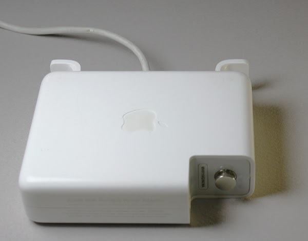
For the teardown I started with a Macbook 85W power supply, model A1172, which is small enough to hold in your palm. The picture below shows several features that can help distinguish the charger from counterfeits: the Apple logo in the case, the metal (not plastic) ground pin on the right, and the serial number next to the ground pin.

Apple 85W Macbook charger

Apple 85W Macbook charger
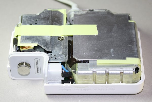
Strange as it seems, the best technique I've found for opening a charger is to pound on a wood chisel all around the seam to crack it open. With the case opened, the metal heat sinks of the charger are visible. The heat sinks help cool the high-power semiconductors inside the charger.

Inside the Apple 85W Macbook charger

Inside the Apple 85W Macbook charger
The other side of the charger shows the circuit board, with the power output at the bottom. Some of the tiny components are visible, but most of the circuitry is covered by the metal heat sink, held in place by yellow insulating tape.

The circuit board inside the Apple 85W Macbook charger.

The circuit board inside the Apple 85W Macbook charger. At the right, screws firmly attach components to the heat sinks.
After removing the metal heat sinks, the components of the charger are visible. These metal pieces give the charger a substantial heft, more than you'd expect from a small unit.

Exploded view of the Apple 85W charger

Exploded view of the Apple 85W charger, showing the extensive metal heat sinks.
The diagram below labels the main components of the charger. AC power enters the charger and is converted to DC. The PFC circuit (Power Factor Correction) improves efficiency by ensuring the load on the AC line is steady. The primary chops up the high-voltage DC from the PFC circuit and feeds it into the transformer. Finally, the secondary receives low-voltage power from the transformer and outputs smooth DC to the laptop. The next few sections discuss these circuits in more detail, so follow along with the diagram below.

The components inside an Apple Macbook 85W power supply.

The components inside an Apple Macbook 85W power supply.

AC enters the charger

AC power enters the charger through a removable AC plug. A big advantage of switching power supplies is they can be designed to run on a wide range of input voltages. By simply swapping the plug, the charger can be used in any region of the world, from European 240 volts at 50 Hertz to North American 120 volts at 60 Hz. The filter capacitors and inductors in the input stage prevent interference from exiting the charger through the power lines. The bridge rectifier contains four diodes, which convert the AC power into DC. (See this video for a great demonstration of how a full bridge rectifier works.)

The input filtering in a Macbook charger. The diode bridge is attached to the metal heat sink with a clip.

The input components in a Macbook charger. The diode bridge rectifier is attached to the metal heat sink with a clip.

PFC: smoothing the power usage

The next step in the charger's operation is the Power Factor Correction circuit (PFC), labeled in purple. One problem with simple chargers is they only draw power during a small part of the AC cycle.[5] If too many devices do this, it causes problems for the power company. Regulations require larger chargers to use a technique called power factor correction so they use power more evenly.

The PFC circuit uses a power transistor to precisely chop up the input AC tens of thousands of times a second; contrary to what you might expect, this makes the load on the AC line smoother. Two of the largest components in the charger are the inductor and PFC capacitor that help boost the voltage to about 380 volts DC.[6]

The primary: chopping up the power

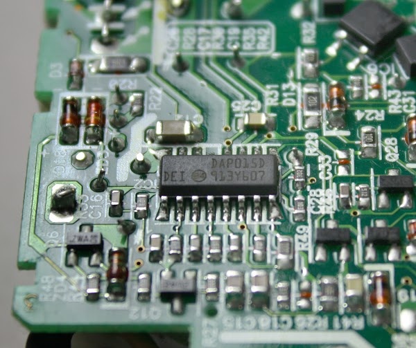
The primary circuit is the heart of the charger. It takes the high voltage DC from the PFC circuit, chops it up and feeds it into the transformer to generate the charger's low-voltage output (16.5-18.5 volts). The charger uses an advanced design called a resonant controller, which lets the system operate at a very high frequency, up to 500 kilohertz. The higher frequency permits smaller components to be used for a more compact charger. The chip below controls the switching power supply.[7]

The circuit board inside the Macbook charger. The chip in the middle controls the switching power supply circuit.

The circuit board inside the Macbook charger. The chip in the middle controls the switching power supply circuit.

The two drive transistors (in the overview diagram) alternately switch on and off to chop up the input voltage. The transformer and capacitor resonate at this frequency, smoothing the chopped-up input into a sine wave.

The secondary: smooth, clean power output

The secondary side of the circuit generates the output of the charger. The secondary receives power from the transformer and converts it DC with diodes. The filter capacitors smooth out the power, which leaves the charger through the output cable.

The most important role of the secondary is to keep the dangerous high voltages in the rest of the charger away from the output, to avoid potentially fatal shocks. The isolation boundary marked in red on the earlier diagram indicates the separation between the high-voltage primary and the low-voltage secondary. The two sides are separated by a distance of about 6 mm, and only special components can cross this boundary.

The transformer safely transmits power between the primary and the secondary by using magnetic fields instead of a direct electrical connection. The coils of wire inside the transformer are triple-insulated for safety. Cheap counterfeit chargers usually skimp on the insulation, posing a safety hazard. The optoisolator uses an internal beam of light to transmit a feedback signal between the secondary and primary. The control chip on the primary side uses this feedback signal to adjust the switching frequency to keep the output voltage stable.

The output components in an Apple Macbook charger. The microcontroller board is visible behind the capacitors.

The output components in an Apple Macbook charger.The two power diodes are in front on the left. Behind them are three cylindrical filter capacitors.The microcontroller board is visible behind the capacitors.

A powerful microprocessor in your charger?

One unexpected component is a tiny circuit board with a microcontroller, which can be seen above. This 16-bit processor constantly monitors the charger's voltage and current. It enables the output when the charger is connected to a Macbook, disables the output when the charger is disconnected, and shuts the charger off if there is a problem. This processor is a Texas Instruments MSP430 microcontroller, roughly as powerful as the processor inside the original Macintosh.[8]

The microcontroller circuit board from an 85W Macbook power supply, on top of a quarter. The MPS430 processor monitors the charger's voltage and current.

The microcontroller circuit board from an 85W Macbook power supply, on top of a quarter. The MPS430 processor monitors the charger's voltage and current.

The square orange pads on the right are used to program software into the chip's flash memory during manufacturing.[9] The three-pin chip on the left (IC202) reduces the charger's 16.5 volts to the 3.3 volts required by the processor.[10]

The charger's underside: many tiny components

Turning the charger over reveals dozens of tiny components on the circuit board. The PFC controller chip and the power supply (SMPS) controller chip are the main integrated circuits controlling the charger. The voltage reference chip is responsible for keeping the voltage stable even as the temperature changes.[11] These chips are surrounded by tiny resistors, capacitors, diodes and other components. The output MOSFET transistor switches the power to the output on and off, as directed by the microcontroller. To the left of it, the current sense resistors measure the current flowing to the laptop.

The printed circuit board from an Apple 85W Macbook power supply, showing the tiny components inside the charger.

The printed circuit board from an Apple 85W Macbook power supply, showing the tiny components inside the charger.
The isolation boundary (marked in red) separates the high voltage circuitry from the low voltage output components for safety. The dashed red line shows the isolation boundary that separates the low-voltage side (bottom right) from the high-voltage side. The optoisolators send control signals from the secondary side to the primary, shutting down the charger if there is a malfunction.[12]

One reason the charger has more control components than a typical charger is its variable output voltage. To produce 60 watts, the charger provides 16.5 volts at 3.6 amps. For 85 watts, the voltage increases to 18.5 volts at 4.6 amps. This allows the charger to be compatible with lower-voltage 60 watt chargers, while still providing 85 watts for laptops that can use it.[13] As the current increases above 3.6 amps, the circuit gradually increases the output voltage. If the current increases too much, the charger abruptly shuts down around 90 watts.[14]

Inside the Magsafe connector

The magnetic Magsafe connector that plugs into the Macbook is more complex than you would expect. It has five spring-loaded pins (known as Pogo pins) to connect to the laptop. Two pins are power, two pins are ground, and the middle pin is a data connection to the laptop.

The pins of a Magsafe 2 connector. The pins are arranged symmetrically, so the connector can be plugged in either way.

The pins of a Magsafe 2 connector. The pins are arranged symmetrically, so the connector can be plugged in either way.
Inside the Magsafe connector is a tiny chip that informs the laptop of the charger's serial number, type, and power. The laptop uses this data to determine if the charger is valid. This chip also controls the status LEDs. There is no data connection to the charger block itself; the data connection is only with the chip inside the connector. For more details, see my article on the Magsafe connector.

The circuit board inside a Magsafe connector is very small. There are two LEDs on each side. The chip is a DS2413 1-Wire switch.

The circuit board inside a Magsafe connector is very small. There are two LEDs on each side. The chip is a DS2413 1-Wire switch.

Operation of the charger

You may have noticed that when you plug the connector into a Macbook, it takes a second or two for the LED to light up. During this time, there are complex interactions between the Macbook, the charger, and the Magsafe connector.

When the charger is disconnected from the laptop, the output transistor discussed earlier blocks the output power.[15] When the Magsafe connector is plugged into a Macbook, the laptop pulls the power line low.[16] The microcontroller in the charger detects this and after exactly one second enables the power output. The laptop then loads the charger information from the Magsafe connector chip. If all is well, the laptop starts pulling power from the charger and sends a command through the data pin to light the appropriate connector LED. When the Magsafe connector is unplugged from the laptop, the microcontroller detects the loss of current flow and shuts off the power, which also extinguishes the LEDs.

You might wonder why the Apple charger has all this complexity. Other laptop chargers simply provide 16 volts and when you plug it in, the computer uses the power. The main reason is for safety, to ensure that power isn't flowing until the connector is firmly attached to the laptop. This minimizes the risk of sparks or arcing while the Magsafe connector is being put into position.

Why you shouldn't get a cheap charger

The Macbook 85W charger costs $79 from Apple, but for $14 you can get a charger on eBay that looks identical. Do you get anything for the extra $65? I opened up an imitation Macbook charger to see how it compares with the genuine charger. From the outside, the charger looks just like an 85W Apple charger except it lacks the Apple name and logo. But looking inside reveals big differences. The photos below show the genuine Apple charger on the left and the imitation on the right.

Inside the Apple 85W Macbook charger (left) vs an imitation charger (right). The genuine charger is crammed full of components, while the imitation has fewer parts.

Inside the Apple 85W Macbook charger (left) vs an imitation charger (right). The genuine charger is crammed full of components, while the imitation has fewer parts.

The imitation charger has about half the components of the genuine charger and a lot of blank space on the circuit board. While the genuine Apple charger is crammed full of components, the imitation leaves out a lot of filtering and regulation as well as the entire PFC circuit. The transformer in the imitation charger (big yellow rectangle) is much bulkier than in Apple's charger; the higher frequency of Apple's more advanced resonant converter allows a smaller transformer to be used.

The circuit board of the Apple 85W Macbook charger (left) compared with an imitation charger (right). The genuine charger has many more components.

The circuit board of the Apple 85W Macbook charger (left) compared with an imitation charger (right). The genuine charger has many more components.

Flipping the chargers over and looking at the circuit boards shows the much more complex circuitry of the Apple charger. The imitation charger has just one control IC (in the upper left).[17] since the PFC circuit is omitted entirely. In addition, the control circuits are much less complex and the imitation leaves out the ground connection.

The imitation charger is actually better quality than I expected, compared to the awful counterfeit iPad charger and iPhone charger that I examined. The imitation Macbook charger didn't cut every corner possible and uses a moderately complex circuit. The imitation charger pays attention to safety, using insulating tape and keeping low and high voltages widely separated, except for one dangerous assembly error that can be seen below. The Y capacitor (blue) was installed crooked, so its connection lead from the low-voltage side ended up dangerously close to a pin on the high-voltage side of the optoisolator (black), creating a risk of shock.

Safety hazard inside an imitation Macbook charger. The lead of the Y capacitor is too close to the pin of the optoisolator, causing a risk of shock.

Safety hazard inside an imitation Macbook charger. The lead of the Y capacitor is too close to the pin of the optoisolator, causing a risk of shock.

Problems with Apple's chargers

The ironic thing about the Apple Macbook charger is that despite its complexity and attention to detail, it's not a reliable charger. When I told people I was doing a charger teardown, I rapidly collected a pile of broken chargers from people who had failed chargers. The charger cable is rather flimsy, leading to a class action lawsuit stating that the power adapter dangerously frays, sparks and prematurely fails to work. Apple provides detailed instructions on how to avoid damaging the wire, but a stronger cable would be a better solution. The result is reviews on the Apple website give the charger a dismal 1.5 out of 5 stars.

Burn mark inside an 85W Apple Macbook power supply that failed.

Burn mark inside an 85W Apple Macbook power supply that failed.

Macbook chargers also fail due to internal problems. The photos above and below show burn marks inside a failed Apple charger from my collection.[18] I can't tell exactly what went wrong, but something caused a short circuit that burnt up a few components. (The white gunk in the photo is insulating silicone used to mount the board.)

Burn marks inside an Apple Macbook charger that malfunctioned.

Burn marks inside an Apple Macbook charger that malfunctioned.

Why Apple's chargers are so expensive

As you can see, the genuine Apple charger has a much more advanced design than the imitation charger and includes more safety features. However, the genuine charger costs $65 more and I doubt the additional components cost more than $10 to $15[19]. Most of the cost of the charger goes into the healthy profit margin that Apple has on their products. Apple has an estimated 45% profit margin on iPhones[20] and chargers are probably even more profitable. Despite this, I don't recommend saving money with a cheap eBay charger due to the safety risk.

Conclusion

People don't give much thought to what's inside a charger, but a lot of interesting circuitry is crammed inside. The charger uses advanced techniques such as power factor correction and a resonant switching power supply to produce 85 watts of power in a compact, efficient unit. The Macbook charger is an impressive piece of engineering, even if it's not as reliable as you'd hope. On the other hand, cheap no-name chargers cut corners and often have safety issues, making them risky, both to you and your computer.

Notes and references

[1] The main alternative to a switching power supply is a linear power supply, which is much simpler and converts excess voltage to heat. Because of this wasted energy, linear power supplies are only about 60% efficient, compared to about 85% for a switching power supply. Linear power supplies also use a bulky transformer that may weigh multiple pounds, while switching power supplies can use a tiny high-frequency transformer.

[2] Switching power supplies were taking over the computer industry as early as 1971. Electronics World said that companies using switching regulators "read like a 'Who's Who' of the computer industry: IBM, Honeywell, Univac, DEC, Burroughs, and RCA, to name a few". See "The Switching Regulator Power Supply", Electronics World v86 October 1971, p43-47. In 1976, Silicon General introduced SG1524 PWM integrated circuit, which put the control circuitry for a switching power supply on a single chip.

[3] The quote about the Apple II power supply is from page 74 of the 2011 book Steve Jobs by Walter Isaacson. It inspired me to write a detailed history of switching power supplies: Apple didn't revolutionize power supplies; new transistors did. Steve Job's quote sounds convincing, but I consider it the reality distortion field in effect.

[4] If anyone can take the credit for making switching power supplies an inexpensive everyday product, it is Robert Boschert. He started selling switching power supplies in 1974 for everything from printers and computers to the F-14 fighter plane. See Robert Boschert: A Man Of Many Hats Changes The World Of Power Supplies in Electronic Design. The Apple II's power supply is very similar to the Boschert OL25 flyback power supply but with a patented variation.

[5] You might expect the bad power factor is because switching power supplies rapidly turn on and off, but that's not the problem. The difficulty comes from the nonlinear diode bridge, which charges the input capacitor only at peaks of the AC signal. (If you're familiar with power factors due to phase shift, this is totally different. The problem is the non-sinusoidal current, not a phase shift.)

The idea behind PFC is to use a DC-DC boost converter before the switching power supply itself. The boost converter is carefully controlled so its input current is a sinusoid proportional to the AC waveform. The result is the boost converter looks like a nice resistive load to the power line, and the boost converter supplies steady voltage to the switching power supply components.

[6] The charger uses a MC33368"High Voltage GreenLine Power Factor Controller" chip to run the PFC. The chip is designed for low power, high-density applications so it's a good match for the charger.

[7] The SMPS controller chip is a L6599 high-voltage resonant controller; for some reason it is labeled DAP015D. It uses a resonant half-bridge topology; in a half-bridge circuit, two transistors control power through the transformer first one direction and then the other. Common switching power supplies use a PWM (pulse width modulation) controller, which adjusts the time the input is on. The L6599, on the other hand, adjusts the frequency instead of the pulse width. The two transistors alternate switching on for 50% of the time. As the frequency increases above the resonant frequency, the power drops, so controlling the frequency regulates the output voltage.

[8] The processor in the charger is a MSP430F2003 ultra low power microcontroller with 1kB of flash and just 128 bytes of RAM. It includes a high-precision 16-bit analog to digital converter. More information is here.

The 68000 microprocessor from the original Apple Macintosh and the 430 microcontroller in the charger aren't directly comparable as they have very different designs and instruction sets. But for a rough comparison, the 68000 is a 16/32 bit processor running at 7.8MHz, while the MSP430 is a 16 bit processor running at 16MHz. The Dhrystone benchmark measures 1.4 MIPS (million instructions per second) for the 68000 and much higher performance of 4.6 MIPS for the MSP430. The MSP430 is designed for low power consumption, using about 1% of the power of the 68000.

[9] The 60W Macbook charger uses a custom MSP430 processor, but the 85W charger uses a general-purpose processor that needs to loaded with firmware. The chip is programmed with the Spy-Bi-Wire interface, which is TI's two-wire variant of the standard JTAG interface. After programming, a security fuse inside the chip is blown to prevent anyone from reading or modifying the firmware.

[10] The voltage to the processor is provided by not by a standard voltage regulator, but a LT1460 precision reference, which outputs 3.3 volts with the exceptionally high accuracy of 0.075%. This seems like overkill to me; this chip is the second-most expensive chip in the charger after the SMPS controller, based on Octopart's prices.

[11] The voltage reference chip is unusual, it is a TSM103/A that combines two op amps and a 2.5V reference in a single chip. Semiconductor properties vary widely with temperature, so keeping the voltage stable isn't straightforward. A clever circuit called a bandgap reference cancels out temperature variations; I explain it in detail here.

[12] Since some readers are very interested in grounding, I'll give more details. A 1KΩ ground resistor connects the AC ground pin to the charger's output ground. (With the 2-pin plug, the AC ground pin is not connected.) Four 9.1MΩ resistors connect the internal DC ground to the output ground. Since they cross the isolation boundary, safety is an issue. Their high resistance avoids a shock hazard. In addition, since there are four resistors in series for redundancy, the charger remains safe even if a resistor shorts out somehow. There is also a Y capacitor (680pF, 250V) between the internal ground and output ground; this blue capacitor is on the upper side of the board. A T5A fuse (5 amps) protects the output ground.

[13] The power in watts is simply the volts multiplied by the amps. Increasing the voltage is beneficial because it allows higher wattage; the maximum current is limited by the wire size.

[14] The control circuitry is fairly complex. The output voltage is monitored by an op amp in the TSM103/A chip which compares it with a reference voltage generated by the same chip. This amplifier sends a feedback signal via an optoisolator to the SMPS control chip on the primary side. If the voltage is too high, the feedback signal lowers the voltage and vice versa. That part is normal for a power supply, but ramping the voltage from 16.5 volts to 18.5 volts is where things get complicated.

The output current creates a voltage across the current sense resistors, which have a tiny resistance of 0.005Ω each - they are more like wires than resistors. An op amp in the TSM103/A chip amplifies this voltage. This signal goes to tiny TS321 op amp which starts ramping up when the signal corresponds to 4.1A. This signal goes into the previously-described monitoring circuit, increasing the output voltage.

The current signal also goes into a tiny TS391 comparator, which sends a signal to the primary through another optoisolator to cut the output voltage. This appears to be a protection circuit if the current gets too high. The circuit board has a few spots where zero-ohm resistors (i.e. jumpers) can be installed to change the op amp's amplification. This allows the amplification to be adjusted for accuracy during manufacture.

[15] If you measure the voltage from a Macbook charger, you'll find about six volts instead of the 16.5 volts you'd expect. The reason is the output is deactivated and you're only measuring the voltage through the bypass resistor just below the output transistor.

[16] The laptop pulls the charger output low with a 39.41KΩ resistor to indicate that it is ready for power. An interesting thing is it won't work to pull the output too low - shorting the output to ground doesn't work. This provides a safety feature. Accidental contact with the pins is unlikely to pull the output to the right level, so the charger is unlikely to energize except when properly connected.

[17] The imitation charger uses the Fairchild FAN7602 Green PWM Controller chip, which is more advanced than I expected in a knock-off; I wouldn't have been surprised if it just used a simple transistor oscillator. Another thing to note is the imitation charger uses a single-sided circuit board, while the genuine uses a double-sided circuit board, due to the much more complex circuit.

[18] The burnt charger is an Apple A1222 85W Macbook charger, which is a different model from the A1172 charger in the rest of the teardown. The A1222 is in a slightly smaller, square case and has a totally different design based on the NCP 1203 PWM controller chip. Components in the A1222 charger are packed even more tightly than in the A1172 charger. Based on the burnt-up charger, I think they pushed the density a bit too far.

[19] I looked up many of the charger components on Octopart to see their prices. Apple's prices should be considerably lower. The charger has many tiny resistors, capacitors and transistors; they cost less than a cent each. The larger power semiconductors, capacitors and inductors cost considerably more. I was surprised that the 16-bit MSP430 processor costs only about $0.45. I estimated the price of the custom transformers. The list below shows the main components.

ComponentCost
MSP430F2003 processor$0.45
MC33368D PFC chip$0.50
L6599 controller chip$1.62
LT1460 3.3V reference$1.46
TSM103/A reference$0.16
2x P11NM60AFP 11A 60V MOSFET$2.00
3x Vishay optocoupler$0.48
2x 630V 0.47uF film capacitor$0.88
4x 25V 680uF electrolytic capacitor$0.12
420V 82uF electrolytic capacitor$0.93
polypropylene X2 capacitor$0.17
3x toroidal inductor$0.75
4A 600V diode bridge$0.40
2x dual common-cathode schottky rectifier 60V, 15A$0.80
20NC603 power MOSFET$1.57
transformer$1.50?
PFC inductor$1.50?

[20] The article Breaking down the full $650 cost of the iPhone 5 describes Apple's profit margins in detail, estimating 45% profit margin on the iPhone. Some people have suggested that Apple's research and development expenses explain the high cost of their chargers, but the math shows R&D costs must be negligible. The book Practical Switching Power Supply Design estimates 9 worker-months to design and perfect a switching power supply, so perhaps $200,000 of engineering cost. More than 20 million Macbooks are sold per year, so the R&D cost per charger would be one cent. Even assuming the Macbook charger requires ten times the development of a standard power supply only increases the cost to 10 cents.

Creating high resolution integrated circuit die photos with Hugin or ICE

$
0
0
Have you ever wanted to take a bunch of photos of an integrated circuit die and combine them into a high-res image? The stitching software can be difficult, so I've written a guide to the process I use. These tips may also be useful for other Hugin panoramas.

The first step is to take a bunch of photos of the die with a microscope. I used an old Motorola 6820 PIA (Peripheral Interface Adapter) chip. This chip had a metal cap over the die that popped off easily with a chisel, exposing the die. The 6820 is notable as the keyboard interface chip in the Apple I computer.

The MC6820 chip with the metal lid popped off to reveal the silicon die.

The MC6820 chip with the metal lid popped off to reveal the silicon die.

The next step is to take photos of the die through a microscope. I used an AmScope metallurgical microscope like the one below. A metallurgical microscope shines the light from above so you can view opaque objects such as chips. (The box on the left of the microscope is the light.) It's much easier if the microscope has an X-Y stage to precisely move the die for each picture.

The key to success is pictures with substantial overlap, so the software can figure out how to combine them. Use more overlap than you think necessary - at least 30% is good. Skimping on the overlap may result in hours of manual work later. The quality of the input photos is also important - make sure the die is level so you can get sharp focus across the whole image. Give the images structured names according to their grid position: 11.png, 12.png, 21.png, ... This will make it much easier to figure out which photos are overlapping neighbors when stitching them together.

For this article, I used the set of images below. Some of them overlap substantially, and some ... not so much. As a result, this article describes a fairly difficult stitch. In the process I learned the importance of overlap, and Hugin worked much better when I tried again with a denser set of images.

The set of images used to generate the die photo.

The set of images used to generate the die photo.

The easiest way to stitch together photos is with Microsoft's Image Composite Editor (ICE). You simply import the photos, click Stitch, and save the result. If ICE works, it's super-easy, but it doesn't have any flexibility if you run into problems (as I did). ICE can be downloaded from Microsoft.

If ICE doesn't work for you, the open-source Hugin panorama photo stitcher is much more flexible and provides many more options. While Hugin is easy to use for simple panoramas, it's pretty confusing for more complex projects, which is why I've written this. The software can be downloaded from the Hugin website. To start a stitch with Hugin, load the images by dragging-and-dropping them into the Photos window. Enter "Normal (rectilinear)" for the lens type and 1 for HFOV in the dialog.

The next step is to generate the control points, which indicate features that match between pairs of images. The control points are what tie the images together, so high quality control points are critical. To generate control points, under "Feature Matching" select "Hugin's CPFind" and click "Create control points". (See the screenshot below.) It will take several minutes to generate control points. You can install other control point finders if you want. Autopano-SIFT-C is said to be good, but I didn't get good results at all with it; it is in a zip file here.

Main screen of the Hugin panorama program

Main screen of the Hugin panorama program

Next, optimize the control points to fit the images together. Under "Optimize", select "Positions (incremental, starting from anchor)" and click "Calculate". Hugin will try to find the best positions for the images. You want a maximum distance of a few pixels, but if you're unlucky the distance may be in the hundreds. Click Yes to apply the optimization.

The Panorama Preview icon will generate a panorama based on the control points. To get the image to the center, click Center and then click the center of the images. Click Fit and it may fit the panorama into the window, or you may need to move the sliders (very slowly). Above the panorama, you can select which images you wish to display. Important: only the selected images will be optimized. If you don't have enough images selected, you'll get the mysterious error "No Feature Points". As you can see below, my first attempt was a mess with all the images in one badly-aligned horizontal strip.

An unsuccessful attempt to generate a composite photo of an IC die with Hugin.

An unsuccessful attempt to generate a composite photo of an IC die with Hugin.

The next step is to fix the control points. Because Hugin optimizes globally, even a few bad control points can mess up the entire image. The main way to fix control points is the Control Points screen, shown below. Select an image on the left and an image on the right. The image selection dialog shows how many control points match between the images. The squares on the images indicate matching control points, which are also listed. If images overlap but don't have any control points, add control points by clicking matching spots in the left and right images. The images will then zoom so you can fine-tune the positions. Finally, click Add.

The control point editing screen in Hugin.

The control point editing screen in Hugin.

A quick way to create control points between two images that overlap is to re-run Hugin's feature mapper on the pair of images. Go to the Photos tab, control-click two images, and then click Create Control Points. If the images overlap sufficiently, Hugin should find control points. If this doesn't work, you're stuck with manually adding points as described above.

If two images shouldn't share control points, go to the Control Points tab, select the two images and delete their control points. This is where organized naming of the images helps - if you see control points between img00 and img35, there's probably something wrong.

You can also clean up bad control points with the control points list. Click the Show Control Points icon at the top and click Distance to sort. You should see a lot of small distances (good) and some very large distances (bad) at the bottom. Click a large distance, and it will bring up the Control Points page. Delete the bad control points. You can also do a bulk delete from the Show Control Points dialog. Click Select by Distance, enter 50 (for example), and then click delete. (But be warned this could delete some good control points too, so you might want to check them first.)

Once the control points are reasonably sensible, go back to the Photos tab and re-optimize. If you're lucky, the images will now be aligned. Unfortunately, I ended up with a cubist mess. I'll explain how to still get a panorama even if you run into problems like this.

Another unsuccessful attempt to make a composite die photo with Hugin.

Another unsuccessful attempt to make a composite die photo with Hugin.

If the parameters get too messed up, select Custom Parameters under Optimize, which will add the Optimizer tab. Under that tab you can reset all the parameters, or parameters for individual images. This is helpful if images start showing up rotated, for instance.

To debug your panorama, you can add images to the panorama one at a time to see which image is causing the problems. Use the Panorama Preview to select the images you want to process. After adding each new image, use the Optimizer tab to optimize the selected images: check "Only use control points between image selected in preview window" and click "Optimize now". If the image shows up in the right spot, all is well. Otherwise, there's something wrong with the last image's control points. Examine its control points under the Control Points tab, and delete any bad matches. (Since integrated circuits often have repeated blocks, it's easy for the matcher to generate convincing but entirely wrong control points.) If the newly-added image doesn't show up at all, it probably lacks any control points linking it with the rest of the images, and got placed at the origin. If the image shows up at an angle, it may have just one control point linking it to another image, letting it swivel around, so add more matching control points. After fixing the image's control points, re-optimize and hopefully it will now be placed correctly. You should be able to correct all the problems by proceeding image by image.

The Panorama Preview window in Hugin. By selecting a subset of the images to tile, control point errors can be corrected one image at a time.

The Panorama Preview window in Hugin. By selecting a subset of the images to tile, control point errors can be corrected one image at a time.

Once you have a good preview, you can generate the final image. Go to the Stitcher tab. Select Equirectangular project. Click Calculate field of view. I recommend starting with a small canvas; it's annoying to wait for a 100 megapixel image and then discover it's a mess. I suggest avoiding cropping; Hugin tends to crop too much, and it's easy to crop later with a tool such as Gimp. Finally, click Stitch, save the project, and wait while the image is generated.

If the result looks good, increase the resolution and generate a high-res version. The photo below shows my final stitched image of the Motorola 6820 die. Click for the full-size image. I've left the image uncropped to make the tiling more visible. I've since made a better composite, starting with source images that overlapped more, and the process was much easier.

Die photo of the Motorola 6820 Peripheral Interface Adapter chip, composited with Hugin.

Die photo of the Motorola 6820 Peripheral Interface Adapter chip, composited with Hugin.

One advanced Hugin feature that may be useful is defining horizontal and vertical lines, so your image comes out straight (wiki). To do this, add control points on a horizontal line between two images, e.g. the upper edge at the left and the upper edge at the right. Note that unlike regular control points, you are not matching the same point in both images, just points on the same horizontal line. After clicking Add, change the mode to Horizontal Line using the dropdown. Put another horizontal edge on the bottom of the die. Vertical lines are similar.

To conclude, making a high-res die photo is an interesting project if you have the right kind of microscope. The Hugin compositing software has a steep learning curve, but hopefully this article will help. Starting with images that overlap significantly will make the process much easier. I should mention that I'm not at all an expert at Hugin or die photos - please leave a comment if you have suggestions.

Acknowledgements: Mikhail at zeptobars gave me helpful advice about Hugin. Other good sites with die photos are Visual 6502 and Silicon Pr0n.

Reverse engineering the ARM1, ancestor of the iPhone's processor

$
0
0
Almost every smartphone uses a processor based on the ARM1 chip created in 1985. The Visual ARM1 simulator shows what happens inside the ARM1 chip as it runs; the result (below) is fascinating but mysterious.[1] In this article, I reverse engineer key parts of the chip and explain how they work, bridging the gap between the puzzling flashing lines in the simulator and what the chip is actually doing. I describethe overall structure of the chip and then descend to the individual transistors, showing how they are built out of silicon and work together to store and process data. After reading this article, you can look at the chip's circuits and understand the data they store.

Simulation of the ARM1 processor chip.

Screenshot of the Visual ARM1 simulator, showing the activity inside the ARM1 chip as it executes a program.

Overview of the ARM1 chip

The ARM1 chip is built from functional blocks, each with a different purpose. Registers store data, the ALU (arithmetic-logic unit) performs simple arithmetic, instruction decoders determine how to handle each instruction, and so forth. Compared to most processors, the layout of the chip is simple, with each functional block clearly visible. (In comparison, the layout of chips such as the 6502 or Z-80 is highly hand-optimized to avoid any wasted space. In these chips, the functional blocks are squished together, making it harder to pick out the pieces.)

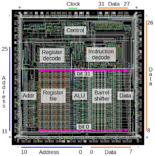
The diagram below shows the most important functional blocks of the ARM chip.[2] The actual processing happens in the bottom half of the chip, which implements the data path. The chip operates on 32 bits at a time so it is structured as 32 horizontal layers: bit 31 at the top, down to bit 0 at the bottom. Several data buses run horizontally to connect different sections of the chip. The large register file, with 25 registers, stands out in the image. The Program Counter (register 15) is on the left of the register file and register 0 is on the right.[3]

The main components of the ARM1 chip. Most of the pins are used for address and data lines; unlabeled pins are various control signals.

The main components of the ARM1 chip. Most of the pins are used for address and data lines; unlabeled pins are various control signals.

Computation takes place in the ALU (arithmetic-logic unit), which is to the right of the registers. The ALU performs 16 different operations (add, add with carry, subtract, logical AND, logical OR, etc.) It takes two 32-bit inputs and produces a 32-bit output. The ALU is described in detail here.[4] To the right of the ALU is the 32-bit barrel shifter. This large component performs a binary shift or rotate operation on its input, and is described in more detail below. At the left is the address circuitry which provides an address to memory through the address pins. At the right data circuitry reads and writes data values to memory.

Above the datapath circuitry is the control circuitry. The control lines run vertically from the control section to the data path circuits below. These signals select registers, tell the ALU what operation to perform, and so forth. The instruction decode circuitry processes each instruction and generates the necessary control signals. The register decode block processes the register select bits in an instruction and generates the control signals to select the desired registers.[5]

The pins

The squares around the outside of the image above are the pads that connect the processor to the outside world. The photo below shows the 84-pin package for the ARM1 processor chip. The gold-plated pins are wired to the pads on the silicon chip inside the package.

The ARM1 processor chip installed in the Acorn ARM Evaluation System. Original photo by Flibble, https://commons.wikimedia.org/wiki/File:Acorn-ARM-Evaluation-System.jpg, CC BY-SA 3.0.

The ARM1 processor chip installed in the Acorn ARM Evaluation System. Full photo by Flibble, CC BY-SA 3.0.

Most of the pads are used for the address and data lines to memory. The chip has 26 address lines, allowing it to access 64MB of memory, and has 32 data lines, allowing it to read or write 32 bits at a time. The address lines are in the lower left and the data lines are in the lower right. As the simulator runs, you can see the address pins step through memory and the data pins read data from memory. The right hand side of the simulator shows the address and data values in hex, e.g. "A:00000020 D:e1a00271". If you know hex, you can easily match these values to the pin states.

Each corner of the chip has a power pin (+) and a ground pin (-), providing 5 volts to run the chip. Various control signals are at the top of the chip. In the simulator, it is easy to spot the the two clock signals that step the chip through its operations (below). The phase 1 and phase 2 clocks alternate, providing a tick-tock rhythm to the chip. In the simulator, the clock runs at a couple cycles per second, while the real chip has a 8MHz clock, more than a million times faster. Finally, note below the manufacturer's name "ACORN" on the chip in place of pin 82.

The two clock signals for the ARM1 processor chip.

History of the ARM chip

The ARM1 was designed in 1985 by engineers Sophie Wilson (formerly Roger Wilson) and Steve Furber of Acorn Computers. The chip was originally named the Acorn RISC Machine and intended as a coprocessor for the BBC Micro home/educational computer to improve its performance. Only a few hundred ARM1 processors were fabricated, so you might expect ARM to be a forgotten microprocessor, a historical footnote of the 1980s. However, the original ARM1 chip led to the amazingly successful ARM architecture with more than 50 billion ARM chips produced. What happened?

In the early 1980s, academic research suggested that instead of making processor instruction sets more complex, designers would get better performance from a processor that was simple but fast: the Reduced Instruction Set Computer or RISC.[6] The Berkeley and Stanford research papers on RISC inspired the ARM designers to choose a RISC design. In addition, given the small size of the design team at Acorn, a simple RISC chip was a practical choice.[7]

The simplicity of a RISC design is clear when comparing the ARM1 and Intel's 80386, which came out the same year: the ARM1 had about 25,000 transistors versus 275,000 in the 386.[8] The photos below show the two chips at the same scale; the ARM1 is 50mm2 compared to 104mm2 for the 386. (Twenty years later, an ARM7TDMI core was 0.1mm2; magnified at the same scale it would be the size of this square vividly illustrating Moore's law.)

Die photo of the ARM1 processor chip. Courtesy of Computer History Museum.Intel 386 CPU die photo (A80386DX-20). By Pdesousa359, https://commons.wikimedia.org/wiki/File:Intel_A80386DX-20_CPU_Die_Image.jpg (CC BY-SA 3.0)

Die photos of the ARM1 processor and the Intel 386 processor to the same scale. The ARM1 is much smaller and contained 25,000 transistors compared to 275,000 in the 386. The 386 was higher density, with a 1.5 micron process compared to 3 micron for the ARM1. ARM1 photo courtesy of Computer History Museum. Intel A80386DX-20 by Pdesousa359, CC BY-SA 3.0.

Because of the ARM1's small transistor count, the chip used very little power: about 1/10 Watt, compared to nearly 2 Watts for the 386. The combination of high performance and low power consumption made later versions of ARM chip very popular for embedded systems. Apple chose the ARM processor for its ill-fated Newton handheld system and in 1990, Acorn Computers, Apple, and chip manufacturer VLSI Technology formed the company Advanced RISC Machines to continue ARM development.[9]

In the years since then, ARM has become the world's most-used instruction set with more than 50 billion ARM processors manufactured. The majority of mobile devices use an ARM processor; for instance, the Apple A8 processor inside iPhone 6 uses the 64-bit ARMv8-A. Despite its humble beginnings, the ARM1 made IEEE Spectrum's list of 25 microchips that shook the world and PC World's 11 most influential microprocessors of all time.

Looking at the low-level construction of the ARM1 chip

Getting back to the chip itself, the ARM1 chip is constructed from five layers. If you zoom in on the chip in the simulator, you can see the components of the chip, built from these layers. As seen below, the simulator uses a different color for each layer, and highlights circuits that are turned on. The bottom layer is the silicon that makes up the transistors of the chip. During manufacturing, regions of the silicon are modified (doped) by applying different impurities. Silicon can be doped positive to form a PMOS transistor (blue) or doped negative for an NMOS transistor (red). Undoped silicon is basically an insulator (black).

The ARM1 simulator uses different colors to represent the different layers of the chip.

The ARM1 simulator uses different colors to represent the different layers of the chip.

Polysilicon wires (green) are deposited on top of the silicon. When polysilicon crosses doped silicon, it forms the gate of a transistor (yellow). Finally, two layers of metal (gray) are on top of the polysilicon and provide wiring.[10] Black squares are contacts that form connections between the different layers.

For our purposes, a MOS transistor can be thought of as a switch, controlled by the gate. When it is on (closed), the source and drain silicon regions are connected. When it is off (open), the source and drain are disconnected. The diagram below shows the three-dimensional structure of a MOS transistor.

Structure of a MOS transistor.

Structure of a MOS transistor.

Like most modern processors, the ARM1 was built using CMOS technology, which uses two types of transistors: NMOS and PMOS. NMOS transistors turn on when the gate is high, and pull their output towards ground. PMOS transistors turn on when the gate is low, and pull their output towards +5 volts.

Understanding the register file

The register file is a key component of the ARM1, storing information inside the chip. (As a RISC chip, the ARM1 makes heavy use of its registers.) The register file consists of 25 registers, each holding 32 bits. This section describes step-by-step how the register file is built out of individual transistors.

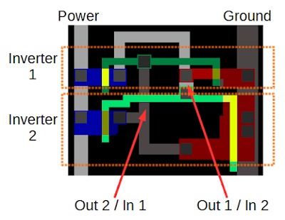
The diagram below shows two transistors forming an inverter. If the input is high (as below), the NMOS transistor (red) turns on, connecting ground to the output so the output is low. If the input is low, the PMOS transistor (blue) turns on, connecting power to the output so the output is high. Thus, the output is the opposite of the input, making an inverter.

An inverter in the ARM1 chip, as displayed by the simulator.

An inverter in the ARM1 chip, as displayed by the simulator.

Combining two inverters into a loop forms a simple storage circuit. If the first inverter outputs 1, the second inverter outputs 0, causing the first inverter to output 1, and the circuit is stable. Likewise, if the first inverter outputs 0, the second outputs 1, and the circuit is again stable. Thus, the circuit will remain in either state indefinitely, "remembering" one bit until forced into a different state.

Two inverters in the ARM1 chip form one bit of register storage.

Two inverters in the ARM1 chip form one bit of register storage.

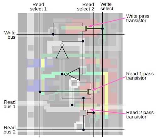
To make this circuit into a useful register cell, read and write bus lines are added, along with select lines to connect the cell to the bus lines. When the write select line is activated, the pass connector connects the write bus to the inverter, allowing a new value to be overwrite the current bit. Likewise, pass transistors connect the bit to a read bus when activated by the corresponding select line, allowing the stored value to be read out.

Schematic of one bit in the ARM1 processor's register file.

Schematic of one bit in the ARM1 processor's register file.

To create the register file, the register cell above is repeated 32 times vertically for each bit, and 25 times horizontally to form each register. Each bit has three horizontal bus lines — the write bus and the two read buses — so there are 32 triples of bus lines. Each register has three vertical control lines — the write select line and two read select lines — so there are 25 triples of control lines. By activating the desired control lines, two registers can be read and one register can be written at a time.[11] When the simulator is running, you can see the vertical control lines activated to select registers, and you can see the data bits flowing on the horizontal bus lines.

By looking at a memory cell in the simulator, you can see which inverter is on and determine if the bit is a 0 or a 1. The diagram below shows a few register bits. If the upper inverter input is active, the bit is 0; if the lower inverter input is active, the bit is 1. (Look at the green lines above or below the bit values.) Thus, you can read register values right out of the simulator if you look closely.

By looking at the ARM1 register file, you can determine the value of each bit. For a 0 bit, the input to the top inverter is active (green/yellow); for a 1 bit, the input to the bottom inverter is active.

By looking at the ARM1 register file, you can determine the value of each bit. For a 0 bit, the input to the top inverter is active (green/yellow); for a 1 bit, the input to the bottom inverter is active.

The barrel shifter

The barrel shifter, which performs binary shifts, is another interesting component of the ARM1. Most instructions use the barrel shifter, allowing a binary argument to be shifted left, shifted right, or rotated by any amount (0 to 31 bits). While running the simulator, you can see diagonal lines jumping back and forth in the barrel shifter.

The diagram below shows the structure of the barrel shifter. Bits flows into the shifter vertically with bit 0 on the left and bit 31 on the right. Output bits leave the shifter horizontally with bit 0 on the bottom and bit 31 on top. The diagonal lines visible in the barrel shifter show where the vertical lines are connected to the horizontal lines, generating a shifted output. Different positions of the diagonals result in different shifts. The upper diagonal line shifts bits to the left, and the lower diagonal line shifts bits to the right. For a rotation, both diagonals are active; it may not be immediately obvious but in a rotation part of the word is shifted left and part is shifted right.

Structure of the barrel shifter in the ARM1 chip.

Structure of the barrel shifter in the ARM1 chip.

Zooming in on the barrel shifter shows exactly how it works. It contains a 32 by 32 crossbar grid of transistors, each connecting one vertical line to one horizontal line. The transistor gates are connected by diagonal control lines; transistors along the active diagonal connect the appropriate vertical and horizontal lines. Thus, by activating the appropriate diagonals, the output lines are connected to the input lines, shifted by the desired amounts. Since the chip's input lines all run horizontally, there are 32 connections between input lines and the corresponding vertical bit lines.

Details of the barrel shifter in the ARM1 chip. Transistors along a specific diagonal are activated to connect the vertical bit lines and output lines. Each input line is connected to a vertical bit line through the indicated connections.

Details of the barrel shifter in the ARM1 chip. Transistors along a specific diagonal are activated to connect the vertical bit lines and output lines. Each input line is connected to a vertical bit line through the indicated connections.

The demonstration program

When you run the simulator, it executes a short hardcoded program that performs shifts of increasing amounts. You don't need to understand the code, but if you're curious it is:
0000  E1A0100F mov     r1, pc        @ Some setup
0004  E3A0200C mov     r2, #12
0008  E1B0F002 movs    pc, r2
000C  E1A00000 nop
0010  E1A00000 nop
0014  E3A02001 mov     r2, #1        @ Load register r2 with 1
0018  E3A0100F mov     r1, #15       @ Load r1 with value to shift
001C  E59F300C ldr     r3, pointer
    loop:
0020  E1A00271 ror     r0, r1, r2    @ Rotate r1 by r2 bits, store in r0
0024  E2822001 add     r2, r2, #1    @ Add 1 to r2
0028  E4830004 str     r0, [r3], #4  @ Write result to memory
002C  EAFFFFFB b       loop          @ Branch to loop
Inside the loop, register r1 (0x000f) is rotated to the right by r2 bit positions and the result is stored in register r0. Then r2 is incremented and the shift result written to memory. As the simulator runs, watch as r2 is incremented and as r0 goes through the various values of 4 bits rotated. The A and D values show the address and data pins as instructions are read from memory.

The changing shift values are clearly visible in the barrel shifter, as the diagonal line shifts position. If you zoom in on the register file, you can read out the values of the registers, as described earlier.

Conclusion

The ARM1 processor led to the amazingly successful ARM processor architecture that powers your smart phone. The simple RISC architecture of the ARM1 makes the circuitry of the processor easy to understand, at least compared to a chip such as the 386.[12] The ARM1 simulator provides a fascinating look at what happens inside a processor, and hopefully this article has helped explain what you see in the simulator.

P.S. If you want to read more about ARM1 internals, see Dave Mugridge's series of posts:
Inside the armv1 Register Bank
Inside the armv1 Register Bank - register selection
Inside the armv1 Read Bus
Inside the ALU of the armv1 - the first ARM microprocessor

Notes and references

[1] I should make it clear that I am not part of the Visual 6502 team that built the ARM1 simulator. More information on the simulator is in the Visual 6502 team's blog post The Visual ARM1.

[2] The block diagram below shows the components of the chip in more detail. See the ARM Evaluation System manual for an explanation of each part.

Floorplan of the ARM1 chip, from ARM Evaluation System manual.

Floorplan of the ARM1 chip, from ARM Evaluation System manual.

[3] You may have noticed that the ARM architecture describes 16 registers, but the chip has 25 physical registers. There are 9 "extra" registers because there are extra copies of some registers for use while handling interrupts.

Another interesting thing about the register file is the PC register is missing a few bits. Since the ARM1 uses 26-bit addresses, the top 6 bits are not used. Because all instructions are aligned on a 32-bit boundary, the bottom two address bits in the PC are always zero. These 8 bits are not only unused, they are omitted from the chip entirely.

[4] The ALU doesn't support multiplication (added in ARM 2) or division (added in ARMv7).

[5] A bit more detail on the decode circuitry. Instruction decoding is done through three separate PLAs. The ALU decode PLA generates control signals for the ALU based on the four operation bits in the instruction. The shift decode PLA generates control signals for the barrel shifter. The instruction decode PLA performs the overall decoding of the instruction. The register decode block consists of three layers. Each layer takes a 4-bit register id and activates the corresponding register. There are three layers because ARM operations use two registers for inputs and a third register for output.

[6] In a RISC computer, the instruction set is restricted to the most-used instructions, which are optimized for high performance and can typically execute in a single clock cycle. Instructions are a fixed size, simplifying the instruction decoding logic. A RISC processor requires much less circuitry for control and instruction decoding, leaving more space on the chip for registers. Most instructions operate on registers, and only load and store instructions access memory. For more information on RISC vs CISC, see RISC architecture.

[7] For details on the history of the ARM1, see Conversation with Steve Furber: The designer of the ARM chip shares lessons on energy-efficient computing.

[8] The 386 and the ARM1 instruction sets are different in many interesting ways. The 386 has instructions from 1 byte to 15 bytes, while all ARM1 instructions are 32-bits long. The 386 has 15 registers - all with special purposes, while the ARM1 has 25 registers, mostly general-purpose. 386 instructions can usually operate on memory, while ARM1 instructions operate on registers except for load and store. The 386 has about 140 different instructions, compared to a couple dozen in the ARM1 (depending how you count). Take a look at the 386 opcode map to see how complex decoding a 386 instruction is. ARM1 instructions fall into 5 categories and can be simply decoded. (I'm not criticizing the 386's architecture, just pointing out the major architectural differences.)

See the Intel 80386 Programmer's Reference Manual and 80386 Hardware Reference Manual for more details on the 386 architecture.

[9] Interestingly the ARM company doesn't manufacture chips. Instead, the ARM intellectual property is licensed to hundreds of different companies that build chips that use the ARM architecture. See The ARM Diaries: How ARM's business model works for information on how ARM makes money from licensing the chip to other companies.

[10] The first metal layer in the chip runs largely top-to-bottom, while the second metal layer runs predominantly horizontally. Having two layers of metal makes the layout much simpler than single-layer processors such as the 6502 or Z-80.

[11] In the register file, alternating bits are mirrored to simplify the layout. This allows neighboring bits to share power and ground lines. The ARM1's register file is triple-ported, so two register can be read and one register written at the same time. This is in contrast to chips such as the 6502 or Z-80, which can only access registers one at a time.

[12] For more information on the ARM1 internals, the book VLSI Risc Architecture and Organization by ARM chip designer Steven Furber has a hundred pages of information on the ARM chip internals. An interesting slide deck is A Brief History of ARM by Lee Smith, ARM Fellow.

Counting bits in hardware: reverse engineering the silicon in the ARM1 processor

$
0
0
How can you count bits in hardware? In this article, I reverse-engineer the circuit used by the ARM1 processor to count the number of set bits in a 16-bit field, showing how individual transistors form multiplexers, which are combined into adders, and finally form the bit counter. The ARM1 is the ancestor of the processor in most cell phones, so you may have a descendent of this circuit in your pocket.

ARM is now the world's most popular instruction set but it has humble beginnings. The original ARM1 processor was designed in 1985 by a UK company called Acorn Computer for the BBC Micro home/educational computer. A few years later Apple needed a low-power, high-performance processor for its ill-fated Newton handheld system and chose ARM.[1] In 1990, Acorn Computers, Apple, and chip manufacturer VLSI Technology formed the company Advanced RISC Machines to continue ARM development. ARM became very popular for low power applications (such as phones) and now more than 50 billion ARM processors have been manufactured.

One way ARM processors increase performance is through block data transfer instructions, which efficiently copy data between on-chip registers and memory storage.[2] These instructions can transfer any subset of ARM's 16 registers in a single instruction. The desired registers are specified by setting the corresponding bits in a 16-bit field in the instruction. To implement the block transfer instructions, the ARM requires two specialized circuits. The first circuit, the bit counter, counts the number of bits set in the register select field to determine how many registers are being transferred.[3] The second circuit, the priority encoder, scans the register select field and finds the next set bit, indicating which register to load/store next.

The ARM1 processor chip with major functional groups labeled. The bit counter and priority encoder used for the LDM/STM instructions are highlighted in red. These take up about 3% of the chip's area.

The ARM1 processor chip with major functional groups labeled. The bit counter and priority encoder used for the LDM/STM instructions are highlighted in red. These take up about 3% of the chip's area.ARM1 die photo courtesy of Computer History Museum.
These two circuits are highlighted in red in the ARM1 die photo above. As you can see, the circuits take up a significant fraction of the chip (about 3%), but the chip designers felt the performance gain from block transfers was worth the increase in chip size and complexity. This article explains the bit counter, and I plan to describe the priority encoder later.

Zooming in on the bit counter reveals the circuit below. It looks like a jumble of lines, but by examining it carefully, you can get an understanding of what is going on. The remainder of the article explains how a special type of circuitry called pass transistor logic is used to build a multiplexer — a circuit that selects one of its two inputs. The multiplexers are used to form logic gates, which are then combined to form a full adder, which adds three bits. Finally, the adders are combined to create the bit counting circuit. If you're not familiar with digital logic or the ARM processor, you might want to start with my earlier article on reverse-engineering the ARM1 for an overview.

The bit counter circuit from the ARM1 processor chip. This circuit counts the number of registers selected by the LDM/STM instructions.

The bit counter circuit from the ARM1 processor chip. This circuit counts the number of registers selected by the LDM/STM instructions.

Pass transistors and transmission gates

The bit counter is built from a type of circuitry called pass transistor logic. Unlike normal logic gates, pass transistor logic switches the inputs themselves to pass an input directly to the output. Pass transistors are used because sums (i.e. XORs) are inconvenient to generate with standard logic and can be generated more efficiently with pass transistor logic.

The ARM1 chip, like most modern chips, is built from a technology called CMOS. The C in CMOS stands for complementary because CMOS circuits are built from two complementary types of transistors. NMOS transistors switch on when the control signal on the gate is high, and can pull the output low. PMOS transistors are opposite; they switch on when the gate's control signal is low, and can pull the output high. Combining an NMOS transistor and a PMOS transistor in parallel forms a transmission gate. If both transistors are on, the input will be passed to the output whether it is low or high. If both transistors are off, the input is blocked. Thus, the circuit acts as a switch that can either pass the input through to the output or block it.

The diagram below shows two transistors (circled) connected to form a transmission gate. The upper one is NMOS and the lower one is PMOS. On the right is the symbol for a transmission gate. Note that because the transistors are complementary, they require opposite enable signals.

Schematic symbols for a CMOS pass gate. On the left, the two transistors are shown. On the right is the equivalent pass gate symbol. The circles around the transistors are to make the transistors clear and are not part of the symbol.

Schematic symbols for a CMOS transmission gate. On the left, the two transistors are shown. On the right is the equivalent transmission gate symbol. The circles around the transistors are to make the transistors clear and are not part of the symbol.

The multiplexer

Next, we can look at how transmission gates are used in the chip. The diagram below shows a multiplexer as it appears in the Visual ARM1 simulator. The ARM1 chip is constructed from five layers, which appear as different colors in the simulator. (The layers are harder to distinguish in the real chip.) The bottom layer is the silicon that makes up the transistors of the chip. During manufacturing, regions of the silicon are modified (doped) by applying different impurities. Silicon can be doped positive to form a PMOS transistor (blue) or doped negative for an NMOS transistor (red). Undoped silicon (black) is basically an insulator. Polysilicon wires (green) are deposited on top of the silicon. When polysilicon crosses doped silicon, it forms the gate of a transistor (yellow). Finally, two layers of metal[4] (gray) are on top of the polysilicon and provide wiring. Black squares are contacts that form connections between the different layers.

A pass-gate multiplexer in the ARM1 processor, showing how different layers are displayed in the Visual ARM1 simulator.

A pass-gate multiplexer in the ARM1 processor, showing how different layers are displayed in the Visual ARM1 simulator.

Each multiplexer consists of four transistors: two NMOS (red) and two PMOS (blue); the gate appears in yellow between the two sides of the transistor. These form two transmission gates allowing either the left input or the right input to be connected to the output. If "Select left" is high and "Select right" is low, the two transistors on the left turn on, connecting the left input to the output. Conversely, if "Select right" is high and "Select left" is low, the two transistors on the right turn on, connecting the right input to the output.

A pass-gate multiplexer circuit in the ARM1 processor. The left shows the physical construction of the circuit, as it appears in the Visual ARM1 simulator. The corresponding schematic is on the right. If 'Select left' is high, the two transistors on the left will be active, connecting the left input to the output. If 'Select right' is high, the two transistors on the right will connect the right input to the output.

A pass-gate multiplexer circuit in the ARM1 processor. The left shows the physical construction of the circuit, as it appears in the Visual ARM1 simulator. The corresponding schematic is on the right. If 'Select left' is high, the two transistors on the left will be active, connecting the left input to the output. If 'Select right' is high, the two transistors on the right will connect the right input to the output.
The symbol for a multiplexer is shown below. If the select line is 1, the input labeled 1 is selected for the output, and conversely for 0. Note that the inverted select line is also required, but isn't explicitly shown in the symbol. This is important, since the inverted select must be generated in the circuit.

Symbol for a two-input multiplexer. Based on the select line, one of the inputs goes to the output.

Symbol for a two-input multiplexer. Based on the select line, one of the inputs goes to the output.

Building a full adder from multiplexers

A full adder is a digital circuit to add two bits along with a carry in, generating a sum output and a carry output. (If you think of the output as a binary sum, the sum output is the low bit and the carry output is the high bit.) Equivalently, the full adder can be thought of as adding three input bits. The full adder is the building block of the ARM1's bit counting circuit.

In the ARM1, a full adder is built from multiplexers, along with a few inverters. The diagram below shows how a full adder appears in the simulator. Counting the yellow rectangles, you can see that there are 29 transistors in the circuit. The transistors are connected by metal wires (gray) and polysilicon wires (green). While the layout may appear chaotic, the transistors are arranged in an orderly way: a row of PMOS transistors (blue), two rows of NMOS transistors (red), and a second row of PMOS transistors (blue).[5]

A full-adder circuit in the ARM1 processor, as it appears in the Visual ARM1 simulator.

A full-adder circuit in the ARM1 processor, as it appears in the Visual ARM1 simulator.
Arranging components for high density wasn't important to the ARM1 designers, so they built circuits from standard blocks (or cells) using computerized design tools, resulting in the regular layout seen above. On the other hand, the designers of earlier processors such as the 6502 and Z-80 tried to minimize the chip size as much as possible, so the chip layout was highly optimized. Each transistor and wire was hand-drawn to fit as tightly as possible, almost like a jigsaw puzzle. The image below shows part of the Z-80 chip, demonstrating the tightly-packed, irregular layout. The difference between hand-draw, optimized layout and computer-generated layout is striking.

A detail of the Z-80 processor layout, showing the complex hand-drawn layout. Each transistor and wire is carefully shaped to minimize the chip's size.

A detail of the Z-80 processor layout, showing the complex hand-drawn layout. Each transistor and wire is carefully shaped to minimize the chip's size. Z-80 data is from the Visual 6502 project.

The schematic below shows how the full adder in the ARM1 is built from multiplexers. In the lower left, a multiplexer generates "A XOR B", which is the single-bit sum of A and B. If you try the combinations of A and B, you'll find that the output is 1 if exactly one of the inputs is 1, and otherwise 0. The next multiplexer reverses the A inputs and computes the complement of A XOR B.[6] The third multiplexer implements a NAND gate: If B is 1 and A is 1, the output is 0.[7]

Schematic of a full-adder in the ARM1 processor, showing its construction from multiplexers. Inverters for A and B are not shown.

Schematic of a full-adder in the ARM1 processor, showing its construction from multiplexers. Inverters for A and B are not shown.

The multiplexers in the upper half compute the sum and carry (i.e. bit 0 and bit 1 of the binary sum), as can be verified by trying the input combinations. You might wonder why inverters are used, rather than generating the desired outputs directly. The reason is to boost the signals, since the outputs of multiplexers are relatively weak.

The diagram below indicates the multiplexers and inverters[6] that make up a full adder, with the components highlighted. Each multiplexer is built as described earlier, and they are arranged as in the schematic above. The multiplexers are connected together by polysilicon and metal wires. The three inputs are at the bottom and the two outputs are at the top. This adder is the main block used to build the bit counter, and the next section will show how adders are connected together.

A full-adder circuit in the ARM1 processor, showing how it is built from pass-gate multiplexers and inverters.

A full-adder circuit in the ARM1 processor, showing how it is built from pass-gate multiplexers and inverters.

Building the bit counter from adders

The bit counter takes 16 bit inputs and generates a 4-bit count as output, using adders as building blocks. The flow chart below shows how it operates, with data flowing from top to bottom. Each box is an adder, with carry (C) and sum (S) outputs. Boxes are colored according to which bit of the sum they are computing: red for the 1's bit, green for the 2's bit, blue for the 4's bit and purple for the 8's bit. Each box passes its sum output down and passes its carry to the left.

Overall, the process is similar to long addition if you could just add three digits at a time. You compute partial sums, then add up those sums, and so forth until all the sums are added up. Then the carries need to be added up, along with the sums of those carries, and so forth. If there are carries from those digits, they need to be added up, until finally everything has been added.

The first step of counting the bits is to add each triple of bits with a full adder, generating a two bit count (0, 1, or 2). Inconveniently, since the sixteen input bits aren't divisible by 3, one bit is left over and is handled separately. Next, the five partial sums are added by more adders (red). As carries are generated, they also get added (green). Carries from the carries are also added (blue). In the final step, two-input half adders[8] compute the sum output; these half adders are simpler than the three-input full adders.[9]

The bit counter in the ARM1 processor is built from full-adders and half adders. Red corresponds to sum bit 0, green is bit 1, blue is bit 2, and purple is bit 3.

The bit counter in the ARM1 processor is built from full-adders and half adders. Red corresponds to sum bit 0, green is bit 1, blue is bit 2, and purple is bit 3. To simplify the diagram, outputs from the first stage are indicated by letters rather than lines.

The diagram below shows how the flow chart above is implemented on the chip to create the entire bit counter circuit. The adders are numbered to match the flow chart. The data bus is at the bottom, connected to the bit counter inputs by 16 polysilicon wires (green). Data flows generally upwards through the circuit, opposite to the flow chart. The five adders at the bottom add triples of input bits, and the remaining adders combine the sums and carries. The four half adders are connected to the output drivers in the upper right. The control circuit enables and disables the output drivers, so the bit count is output to the bus at the right times.

The bit counter circuit in the ARM1 processor. The full-adders and half-adders are indicated with numbers. The bits enter and the bottom and the count is output at the upper right.

The bit counter circuit in the ARM1 processor. The full-adders and half-adders are indicated with numbers. The bits enter and the bottom and the count is output at the upper right.

Conclusion

Well, it's been quite a journey from individual transistors to the bit counter, a complex functional block in a real processor. Hopefully this article has taken some of the mystery out of how circuits in a processor are constructed. Now you can try out the Visual ARM1 simulator and take a look at this circuit in action.[10]

Notes and references

[1] An interesting interview with Steve Furber, co-designer of the ARM1, explains how ARM achieved low power consumption. Acorn wanted to use a low-cost plastic package for the chip, but it could only handle 1 Watt. The designers didn't have good tools for estimating power consumption, so they were conservative in their design and the final power consumption was way below the target, just 1/10 Watt. In addition, ARM1 had a simple RISC (Reduced Instruction Set Computer) design, which also reduced power consumption: ARM1 had about 25,000 transistors compared to 275,000 in the 80386 which came out the same year. Thus, the low power consumption of ARM that led to its wild success in mobile applications was largely accidental.

[2] ARM's block data transfer instructions are called STM (Store Multiple) and LDM (Load Multiple), storing and loading multiple registers with one instruction. These instructions don't exactly fit the RISC processor philosophy since they are fairly complex and perform many memory accesses, but the ARM designers took the pragmatic approach and implemented them for efficiency. These instructions can be used for copying data or for stack push/pop, saving registers in a subroutine call or interrupt handler. Note that these instructions are not implemented in microcode, but in hardware that steps through the registers and memory.

[3] It's not obvious why a bit counter is required at all. You'd think the chip could just store registers until it's done, without knowing the total count. The unexpected answer is that LDM/STM always start with the lowest address working upwards. For example, if you're popping 4 registers off the stack with LDM, you'd expect to start at the top of the stack and work down. Instead, the ARM pulls registers out of the middle of the stack: it starts four words from the top, pops registers in reverse order going up, and then updates the stack pointer to the bottom. The results are exactly the same as popping from the top, just the memory accesses are in the reverse order. (The STM instruction is explained in detail on the ARMwiki.) Thus, the bit counter is needed to figure out how far down to jump in memory at the start of the instruction.

That raises the question of why would memory accesses always go low to high, even when that seems backwards. The explanation is that you want to update register 15 (the program counter) last, so if there's a fault during the instruction you haven't clobbered the instruction address and can restart. This problem was discovered partway through the ARM1 design, causing the designers to implement the new strategy that block transfers always go from lowest register to highest register and lowest address to highest address. The bit counter was added to support this. Some remnants of the earlier, simpler design are visible in the ARM1. Specifically, the priority encoder can operate either direction, but high-to-low is never used. In addition, the address incrementer can both increment and decrement addresses, but decrement is never used. The unused circuitry was removed from the later ARM2.

[4] At the time, having two layers of metal in the chip instead of one was a risky technology. However, the ARM1 designers wanted the convenience of two layers, which made routing the chip much simpler.

[5] A few other things to point out in the multiplexer layout. Note that the second input to each multiplexer matches the first input to the next multiplexer. This lets neighboring multiplexers share inputs, so they can be packed together more closely. Another thing of interest is the transistor sizes. The PMOS transistors are about twice the size of the NMOS transistors in order to provide the same current. The reason is that electrons carry the charge around in NMOS transistors, while "holes" carry the charge in PMOS transistor, and electrons move faster, providing more current (details). Finally, the transistors in the upper right are larger. These transistor drive the outputs from the multiplexer, so they must provide more current.

[6] You might wonder why the circuit computes the complement of A XOR B when it isn't used in the schematic. The reason is the multiplexer uses both the select input and the complement of the select input. Thus, the complement is used; it just isn't explicitly shown in the schematic. Likewise an inverter complements B, so it is available for the select lines.

[7] It is very unusual to implement a NAND gate with a multiplexer. Normally CMOS circuits implement a NAND gate with a standard four transistor circuit. But since the circuit already had multiplexers, adding an additional one was more efficient than the standard NAND gate.

[8] The half adder is built from standard gates, rather than multiplexers, as shown in the schematic below. The half adder's behavior is different from a standard half adder: it computes A+B+1 instead of A+B. Thus, the output of the four half adders is equivalent to adding binary 1111 to the sum, equivalent to subtracting 1. The output drivers invert this, so the output on the bus is the twos complement of the sum. The outputs are also shifted two bits on the bus, multiplying the value by 4 (since ARM registers are 4 bytes long). For example, if you pop 3 registers the stack will be decremented by 12 bytes.

The half-adder circuit from the ARM1 processor's bit counter. The outputs from this half-adder are different from normal, as it is used to generate a twos-complement negative output.

The half-adder circuit from the ARM1 processor's bit counter. The outputs from this half-adder are different from normal, as it is used to generate a twos-complement negative output.

[9] The circuit complexity of the bit counter is interesting. To sum 16 bits requires 15 adders. In general, summing N bits will require N-1 adders (for N a power of 2). Note that each adder takes 3 lines down to 2, so reducing N lines down to 1output requires N-1 adders. (There are 4 outputs, not 1, but the half adders bump the total back to N-1). The number of adders for each output bit is a power of 2: 1 purple, 2 blue, 4 green, 8 red. Larger sum circuits could be created by combining two smaller ones. For example, two 16-bit counter circuits could be combined to create a 32-bit counter circuit by adding four more full adders to add the results from each half, before the final half-adder layer. The circuit used in the ARM1 isn't quite the recursive design, pushing more adders to the first layer. An important part of the design is to minimize propagation delay; in the ARM1 design, signals go through 6 adders in worst case, slightly better than the purely recursive design.

[10] Thanks to the Visual 6502 team for providing the simulator and ARM1 chip layout data. If you're interested in ARM1 internals, also see Dave Mugridge's series of posts.

More ARM1 processor reverse engineering: the priority encoder

$
0
0
In this article, I reverse-engineer the priority encoder in the ARM1 processor. By examining the chip layout provided by the Visual ARM1 project, I have determined how this circuit works and created a schematic.

The ARM1 chip is the ancestor of the extremely popular ARM processors used in most smart phones. The ARM1 is a good choice for reverse engineering since it was designed in 1985 and its simple RISC silicon circuits are easier to understand than modern processors. This article jumps into the chip details; if you want an overview of the ARM1 internals, start with my first article on reverse engineering the ARM1.

The priority encoder takes a 16-bit binary field, finds the bits that are set and outputs the 4-bit binary positions of these bits in sequence. For example, if the input field is 1000000000001011, successive outputs will be 0, 1, 3, and 15. (Bits are scanned starting with bit 0, the rightmost bit.) The priority encoder gets its name because it selects bits by priority (rightmost first) and encodes the result into binary.

The diagram below shows the layout of the priority encoder on the chip. It is implemented as 16 bit slices, one for each bit, arranged left to right ("backwards"). Slice 2 is highlighted in red; slices 5 through 13 have been cut out to make the image fit. The 16 input bits arrive through the data bus on the bottom and each bit enters a slice through one of the bit input lines (green). If the bit is currently the highest priority, the output encoder at the top of the slice generates the 4-bit binary value on the output bus. The pullups pull the output bus lines to the high state. Finally, the drivers amplify the output signals and send them to other parts of the chip.[1]

The priority encoder circuit in the ARM1 consists of 16 slices, one for each bit. One slice is highlighted in red.

The priority encoder circuit in the ARM1 consists of 16 slices, one for each bit. One slice is highlighted in red. Slices 5 to 13 are omitted.

The priority encoder is a key part of the ARM processor's block data transfer instructions, which efficiently copy data between on-chip registers and memory storage.[2] These instructions can transfer any subset of ARM's 16 registers in a single instruction. The desired registers are specified by setting the corresponding bits in a 16-bit field in the instruction. The role of the priority encoder is to scan this field and determine which register to transfer during each step of the operation.

Implementation of the priority encoder

The schematic below shows one of the 16 slices in the priority encoder. The input bit from the bus, bus_bit enters at the bottom. The green bit select block determines if the bit is currently the high-priority bit. If so, bit_selected becomes 1. The output encoder (blue) puts the binary value associated with the selected bit onto the bus. Finally, the bit used latch (red) marks the bit as used, blocking it and allowing the next bit in sequence to be active in the next cycle. The two-phase clock signals Φ1 and Φ2 cause the priority encoder to move from bit to bit.

Schematic of the priority encoder in the ARM1 processor, showing one slice.

Schematic of the priority encoder in the ARM1 processor, showing one slice.

The bit selection logic (green) is fairly straightforward. The input clear_to_left is 1 if all the bits to the left are clear. If all the bits to the left are clear and the current bit is set, then this bit is selected by the priority encoder. This also blocks clear_to_left from being passed to the next slice. Otherwise, clear_to_left is passed along. Thus, as it passes through the circuit clear_to_left will be 1 until a bit is encountered, and then 0 from that point. If the final clear_to_left output is 1, then all bits are clear and encoding is done. The logic for clear_to_right is similar, allowing the highest-priority bit to be selected from the right instead. Normally the initial clear_to_left input is 0, and the initial clear_to_right bit is 1, enabling the left scan and disabling the right scan.

The bit used latch (red) keeps track of which bits have already been output. It is what allows the priority encoder to move from bit to bit each clock cycle. The two transmission gates (indicated with the four-triangle symbol) are clocked alternately so the bit_selected signal will move through the circuit after two half-clocks. Two NAND gates are connected as an SR latch to store this signal. Once a slice has selected a bit, the latch remembers that the bit has been used and blocks bus_bit from flowing into the bit select circuit. This allows the next bit in sequence to be selected. The bit used circuit also has a clear signal that resets the latch for a new instruction.

The bus pullup circuit (purple) and the output encoder (blue) work together to output the binary value corresponding to the selected bit. They use dynamic logic rather than standard gates to reduce the circuit size. This logic depends on the the clock and the capacitance of the output bus lines to generate the right values. In phase 2 of the clock, the bus pullup transistors pull the output bus lines high. Then, in phase 1, the output encoder in the active slice pulls the appropriate lines low so the bus will have the correct value. The schematic above shows the encoder for slice 6: the transistors attached to lines 8 and 1 pull them low, leaving 4 and 2 high; the resulting binary 0110 is 6. One set of pullup transistors supports the whole priority encoder, while each slice has its own output encoder transistors.

The output bus lines pass through drivers to boost the current; the signal on the output bus is relatively weak since it is generated by dynamic logic. The output flows to the register select circuit to select the appropriate register for the data transfer. See Dave Mugridge's article on ARM1 register selection for details on how registers are selected.

Discussion

The block data move transfer instructions in the ARM1 require two special functional units: the priority encoder and the bit counter (which I reverse-engineered earlier). These two circuits are highlighted in red in the ARM1 die photo below. Supporting block data transfers added significant complexity to the chip (about 3% by area), but the chip designers felt the performance gain from block transfers was worth it.

The ARM1 processor chip with major functional groups labeled. The bit counter and priority encoder used for the LDM/STM instructions are highlighted in red. These take up about 3% of the chip's area.

The ARM1 processor chip with major functional groups labeled. The bit counter and priority encoder used for the LDM/STM instructions are highlighted in red. These take up about 3% of the chip's area.ARM1 die photo courtesy of Computer History Museum.

One interesting thing about the priority encoder's design is alternating slices have inverted logic: NAND gates become NOR gates and vice versa. The reason is to avoid inverters between stages. You'll note on the schematic that the clear_to_right and clear_to_left outputs are inverted. The obvious design would add inverters to fix the polarity. However, this would add an extra gate delay in each stage, which is significant when the signal has to ripple through 16 stages. By "flipping" alternate stages, this delay is avoided. The trick of alternating stages to avoid inverters is used in other chips. For example, the 8085's incrementer and the 6502's ALU.

One surprise with the ARM1 priority encoder is it supports both low-to-high priority and high-to-low priority, but high-to-low priority is disabled and not used. That is, the rightmost clear_to_right is wired to 1, so the rightmost bit circuitry will never be active. The explanation for this unused circuitry is interesting.

When using the block data operations to push and pull registers on the stack, you'd expect to push R0, R1, R2, etc and then pop in the reverse order R2, R1, R0.[3] To handle this, the priority encoder needs to provide the registers in either order, and the address incrementer needs to increment or decrement addresses depending on whether you're pushing or popping, and the chip includes this circuitry. However, there's a flaw that wasn't discovered until midway through the design of the ARM1. Register 15 (the program counter) must always be updated last, or else you can't recover from a fault during the instruction because you've lost the address.[4]

The solution used in the ARM1 is to always read or write registers starting with the lowest register and the lowest address. In other words, to pop R2, R1, R0, the ARM1 jumps into the middle of the stack and pops R0, R1, R2 in the reverse order. It sounds crazy but it works. (The bit counter determines how many words to shift the starting position.) The consequence of this redesign was that the circuitry to decrement addresses and priority encode in reverse order is never used. This circuity was removed from the ARM2.

Conclusion

The priority encoder is a large functional unit in the ARM1 chip, used for the block data transfer instructions. By looking at one of the 16 slices in the encoder, the circuit can be reverse-engineered and understood. While largely built from standard logic gates, the circuit also uses transmission gates and dynamic logic for efficiency. One surprise is the priority encoder contains unused logic allowing it to work in either direction. This wasted circuitry is left over from a design change during the development of the ARM1.

Now that you've seen the internals of the priority encoder, you can use the Visual ARM1 simulator to see the circuit in action.[5]

Notes and references

[1] The drivers also invert and buffer clock signals that are used by the priority encoder.

[2] ARM's block data transfer instructions are called STM (Store Multiple) and LDM (Load Multiple), storing and loading multiple registers with one instruction. These instructions can be used for copying data or for stack push/pop, saving registers in a subroutine call or interrupt handler. Note that these instructions are not implemented in microcode, but in hardware that steps through the registers and memory. These instruction are explained in detail on the ARMwiki.

[3] The block data transfer instructions work for general register copying, not just pushing and popping to a stack. It's simpler to explain the instructions in terms of a stack, though.

[4] If an instruction encounters a memory fault (e.g. a virtual memory page is missing), you want to take an interrupt, fix the problem (e.g. load in the page), and then restart the instruction. However, if you update registers high-to-low, R15 (the program counter) will be updated first. If a fault happens during the instruction, the address of the instruction (R15) is lost, and restarting the instruction is a problem.

One solution would be to push registers high-to-low and pop low-to-high so R15 is always updated last. Apparently the ARM designers wanted the low register at the low address, even if the stack grows upwards, so popping R15 least wouldn't work. Another alternative is to have a "shadow" program counter that can restore the program counter during a fault. The ARM1 designers considered this alternative too complex. For details, see page 248 of "VLSI RISC Architecture and Organization", by Stephen Furber, one of the ARM1's designers.

[5] Thanks to the Visual 6502 team for providing the simulator and ARM1 chip layout data. If you're interested in ARM1 internals, also see Dave Mugridge's series of posts.

Conditional instructions in the ARM1 processor, reverse engineered

$
0
0
By carefully examining the layout of the ARM1 processor, it can be reverse engineered. This article describes the interesting circuit used for conditional instructions: this circuit is marked in red on the die photo below. Unlike most processors, the ARM executes every instruction conditionally. Each instruction specifies a condition and is only executed if the condition is satisfied. For every instruction, the condition circuit reads the condition from the instruction register (blue), evaluates the condition flags (purple), and informs the control logic (yellow) if the instruction should be executed or skipped.

The ARM1 processor chip showing the condition evaluation circuit (red) and the main components it interacts with. Original photo courtesy of Computer History Museum.

The ARM1 processor chip showing the condition evaluation circuit (red) and the main components it interacts with. Original photo courtesy of Computer History Museum.

Why care about the ARM1 chip? It is the highly-influential ancestor of the extremely popular ARM processor. The ARM1 processor got off to a slow start in 1985 but now ARM processors are now sold by the tens of billions; your smart phone probably runs on ARM. This article is part of my series on reverse engineering the ARM1; start with my first article for an overview of the chip.

What are conditional instructions?

A key part of any computer is the ability of a program to change what it is doing based on various conditions. Most computers provide conditional branch instructions, which cause execution to jump to a different part of the program based on various condition flags. For example, consider the code if (x == 0) { do_something }. Compiled to assembly code, this first tests the value of variable x and sets the Zero flag if x is 0. Next, a conditional branch instruction jump over the do_something code if the Zero flag is not set.

The ARM processor takes conditionals much further than other processors: every instruction becomes a conditional instruction. Every instruction includes one of 16 conditions and the instruction is only executed if the condition is true; otherwise the instruction is skipped. (This is also known as predication.) The motivation is to avoid inefficient jumping around in the code.

The ARM manual excerpt below shows how four bits in each 32-bit instruction specify one of 16 conditions. Most of the conditions are straightforward, checking if values are equal, negative, higher, and so forth. Most instructions will use the "always" condition, which simply means the instruction always executes. The opposite "never" condition is not highly useful - an instruction with that condition never executes - but it can be used for a NOP, patching code, or adjusting timing of an instruction sequence.

Every instruction in the ARM processor has one of 16 conditions specified. The instruction is executed only if the condition is satisfied.

Every instruction in the ARM processor has one of 16 conditions specified. The instruction is executed only if the condition is satisfied.

Studying the different conditions reveals much of how the condition circuit works. It is based on four condition flags. The zero (Z) flag is set if a value is zero. The negative (N) flag is set if a value is negative. The carry (C) flag is set if there is a carry or borrow from addition or subtraction. The overflow (V) flag is set if there is an overflow during signed arithmetic (details).

The top three bits of the instruction select one of eight conditions, as highlighted in yellow. The fourth bit selects the condition or its opposite (blue). If the fourth bit is 0, the condition must be true; if the fourth bit is 1, the condition must be false.

Implementation of the circuit

The implementation of the conditional logic circuit matches the above description. First, the eight conditions are generated from the four flags. One of the conditions is selected based on the three instruction bits. If the fourth instruction bit is set, the condition is flipped. The result is 1 if the condition is satisfied, and 0 if the condition is not satisfied. One unexpected part of the circuit is that an undefined instruction or and interrupt causes the condition to be cleared, preventing execution of the instruction. The resulting condition signal output is connected to a control part of the chip, where it causes the instruction to be executed or not, as desired.

The condition code evaluation circuit from the ARM1 processor.

The condition code evaluation circuit from the ARM1 processor.

The diagram above shows the condition code circuit of the chip as it appears in the simulator; this is a zoomed-in version of the red rectangle indicated on the die earlier. The chip consists of multiple layers, indicated by different colors. Transistors appear as red or blue regions. NMOS transistors are red; they turn on with a 1 input and can pull their output low. PMOS transistors (blue) are complementary; they turn on with a 0 input and can pull their output high. Physically above the transistors is the polysilicon wiring layer (green). When polysilicon crosses a transistor it forms the gate (yellow) that controls the transistor. Finally, two layers of metal wiring (gray) are above the polysilicon.

The circuit is arranged in columns. The first column of transistors forms the logic gates to generate the conditions from the flag values. The next column is the multiplexer, a circuit that takes the eight input conditions and selects one. The rightmost column contains 8 NAND gates that decode the three instruction bits into 8 control lines. Each line is fed into the multiplexer to select the corresponding condition. At the right is the wiring for the 3 instruction bits and their complements. A few miscellaneous gates are at the bottom of the multiplexer and decoder columns. These include inverters to complement the instruction bits.

The condition generation gates

The diagram below zooms in on the left third of the circuit above. This part of the circuit uses standard CMOS logic gates to computes the conditions from the flags. Each gate is built from NMOS (red) and PMOS (blue) transistors in a horizontal strip. Comparing the text description of conditions from the manual with the logic shows how the conditions are generated. For instance, the HI (unsigned higher) condition requires flags "C set and Z clear". The top three gates generate this condition. The GE (greater than or equal) condition is more complex, requiring flags "N set and V set, or N clear and V clear". The next two gates compute this value. (Due to the way CMOS gates are constructed, an OR-NAND gate is constructed as a single gate.) Likewise, the other conditions are generated. The AL (always) condition is simply a 1, and doesn't require any circuitry. The conditions are fed into the multiplexer, which will be discussed below.

The output coming back from the multiplexer is the selected condition, labeled "cond" below. The NAND and OR-NAND gates flip the condition if instruction register bit 28 (ireg28) is set. This implements the eight opposite conditions. The result is labeled "ok", indicating the overall condition is satisfied. The final three gates block instruction execution for an interrupt or undefined instruction.

Gates in the ARM1 processor generate the various conditionals from the flag values.

Gates in the ARM1 processor generate the various conditionals from the flag values.

One thing I'd like to emphasize about the ARM1 is that its layout is very orderly and non-optimized. While it may appear chaotic, the gates are arranged by combining relatively fixed blocks ("standard cells") and wiring them together. Each gate forms a strip and the gates are stacked together in columns. The polysilicon and metal layers connect the gates as necessary.

The layout of the ARM1 chip is a consequence of the VLSI Technology chip design software used to create it. The resulting layout is simple, but doesn't use space very efficiently. Since the ARM1 uses very few transistors for its time, the designers weren't worried about optimizing the layout. In contrast, earlier chips such as the Z-80 were hand-drawn, with each transistor and wire carefully shaped to use the minimum space possible. The diagram below shows a small part of the Z-80 processor layout, showing the extremely irregular but dense arrangement of the chip. The transistors are not arranged in rows as in the ARM1 above, but fit together to use all the available space.

A detail of the Z-80 processor layout, showing the complex hand-drawn layout. Each transistor and wire is carefully shaped to minimize the chip's size.

A detail of the Z-80 processor layout, showing the complex hand-drawn layout. Each transistor and wire is carefully shaped to minimize the chip's size.

The multiplexer and decoders

Selecting the desired condition out of the eight possibilities is the job of a circuit called the multiplexer. The multiplexer takes 8 inputs (the conditions) and 8 control signals (based on the instruction) and selects the desired condition. To the right of the multiplexer, 8 NAND gates generate the 8 control signals by decoding the three instruction bits. Each gate simply looks at three bit values and outputs a 0 if the bits select that condition. For instance, if the first two bits are 0 and the third is 1, the gate for condition 1 outputs a 0, selecting that condition in the multiplexer. The animation below shows the circuit as the instruction bits cycle through the eight conditions. You can see the activated condition moving downwards through the circuit.

Animation of the multiplexer in the ARM1 condition code evaluation circuit.

Animation of the multiplexer in the ARM1 condition code evaluation circuit.

While a multiplexer can be built from standard logic gates, the ARM1 multiplexer is built from a different type of circuitry called transmission gates (which the ARM1 also uses in its bit counter). A multiplexer built from transmission gates is more compact and faster than one built from standard logic (NAND gates). One feature of CMOS is that by combining an NMOS transistor and a PMOS transistor in parallel, a transmission gate switch can be built. Feeding 1 into the NMOS gate and 0 into the PMOS gate turns on both transistors and they pass their input through. With the opposite gate values, both transistors turn off and the switch opens. The multiplexer is built from 8 of these CMOS switches. Each condition input feeds into one switch, and the switch outputs are connected together. One switch is turned on at a time, selecting the corresponding input as the output value.

The diagram below shows the schematic of the multiplexer as well as its physical layout on the chip. Only the first three segments of the eight are shown; the remainder are similar. Each input is connected to two transistors forming a CMOS switch. Because the NMOS and PMOS gates require opposite signals, the multiplexer has an inverter for each control signal. Each inverter also consists of two transistors, but wired differently from the switch.

Schematic of the multiplexer inside the ARM1 processor's condition code evaluation circuit.Diagram of the multiplexer inside the ARM1 processor's condition code evaluation circuit.

Schematic and diagram of the multiplexer inside the ARM1 processor's condition code evaluation circuit.

Working together the decode circuit, inverters, and CMOS switches form the multiplexer that selects the desired condition from the eight choices. The logic described earlier allows this condition to be flipped, for a total of 16 possible conditions.

Conclusion

One unusual feature of the ARM instruction set is that every instruction has a condition associated with it and is only executed if the condition is true. The ARM1 chip is simple enough that the condition circuitry on the chip can be examined and understood at the transistor and gate level. Now that you've seen the internals of the condition logic, you can use the Visual ARM1 simulator to see the circuit in action. While the ARM1 may seem like a historical artifact of the 1980s, ARM processors power most smartphones, so there's probably a similar circuit controlling your phone right now.

Thanks to the Visual 6502 team for providing the simulator and ARM1 chip layout data. If you're interested in ARM1 internals, see my full set of ARM posts and Dave Mugridge's series of posts.

The ARM1 processor's flags, reverse engineered

$
0
0

This article reverse-engineers the flag circuits in the ARM1 processor, explaining in detail how the flags are generate, controlled, and used. Condition flags are a key part of most computers, since they allow the computer to change what it does based on various conditions. The flags keep track of conditions such as a value being negative or zero or an overflow happening. Processors may also have status flags to control modes such as running in user mode versus protected (kernel) execution. The ARM1 processor stores these flags in a special register called the Processor Status Register (PSR).[1]

The ARM1 chip is interesting to examine not only because it is simple enough to understand but also because it was the first ARM processor. There are now tens of billions of ARM processors in use, probably powering your smartphone right now. This article is part of my series on reverse-engineering the ARM1. Processor flags seem like they should be trivial, but there's a lot more involved than you might expect. You might want to start with my first article for an overview of the chip.

The die photo below shows the ARM1 chip. This article concentrates on the flag logic, highlighted in red. As you can see, flags take up a significant part of the chip. The flags interact with many other parts of the chip: the trap control logic handles interrupts and exceptions; the register control logic handles access to the chip's registers including the program counter (PC); when the Arithmetic-Logic Unit (ALU) performs computations it stores status in the flags; the Barrel Shifter shifts or rotates values, sending shifted bits to the flags; and the Instruction Register holds instructions as they are read from memory and feeds them to the decode logic to be interpreted. In the upper left, the M0 and M1 pins indicate the mode bits stored in the flags. The article will describe how all these components interact with the flags.

The flag circuitry in the ARM1 processor interacts with many other components of the chip.

The flag circuitry (red) in the ARM1 processor interacts with many other components of the chip. Original photo courtesy of Computer History Museum.

Some ARM1 background

This section summarizes a few features of the ARM1 processor that are important for understanding the flags. The ARM1 is a 32-bit processor with 16 32-bit registers called R0 through R15 (and some extra registers that will be described later). The processor has a 26-bit address space.

One unusual feature of the ARM1 processor is it combines the flag bits in the processor status register (PSR) and the program counter (PC) into a single register, R15, the PC/PSR. Because of the 26-bit address space, the top 6 bits of the 32-bit PC register are unused. In addition, instructions are always aligned on a 32-bit boundary, so the bottom two PC bits are always 0. These eight unused PC bits were instead used for flags, as shown in the diagram below.[2]

The Processor Status Register in the ARM1 processor is combined with the program counter.

The Processor Status Register in the ARM1 processor is combined with the program counter. From page 2-26 of the ARM databook.

Four condition flags hold the status of arithmetic operations or comparisons. The negative (N) flag indicates a negative result. The zero (Z) flag indicates a zero result. The carry (C) flag indicates a carry from an unsigned value that doesn't fit in 32 bits. The overflow (V) flag indicates an overflow from a signed value that doesn't fit in 32 bits. The next two bits are used to enable or disable interrupts: the I flag controls regular interrupts, while the F flag controls the chip's special fast interrupts. The bottom two bits (M1 and M0) control the processor's execution mode: user, supervisor (kernel), interrupt handler, or fast interrupt handler. These modes will be discussed in more detail later.

Two instruction classes that are important to flags are the data processing instructions and the block data transfer instructions. Since the ARM has a simple, orthogonal instruction set, these operations can operate on the R15 with the flags as easily as any of the other registers.

The data processing instructions are the arithmetic-logic instructions. There are 16 types of data processing operations, such as addition, subtraction, Boolean operations such as AND, and comparison. Unlike most processors, the ARM makes updates of the condition flags optional. The instruction includes a bit called the "S" bit. If the S bit is set, the instruction updates the condition flags; otherwise the flags remain unchanged. The data processing instructions can also act on R15 directly, causing the flags to be read or modified.

The ARM also provides block data transfer instructions: LDM (load multiple) and STM (store multiple). These instructions load a selected set of registers from memory or store them to memory, for example popping registers from the stack or pushing them to the stack. These instructions can also use R15, accessing or modifying the flags.

Floorplan of the ARM1 chip, from ARM Evaluation System manual. (Bus labels are corrected from original.)

Floorplan of the ARM1 chip, from ARM Evaluation System manual. (Bus labels are corrected from original.)

While the program counter (PC) and flags are architecturally part of the same register R15, they are physically separated on the chip, as you can see from the die photo and the floorplan diagram above. The flags are labeled PSR, above the ALU, while the PC is on the left of the register file. Interestingly, the original sketch for the ARM1 (below) show the PSR flags right next to the PC. While the final chip architecture largely matched the sketch, some components moved. In particular, several functional units were moved to the top of the chip, above the instruction bus (orange).

Original sketch of the ARM1 chip layout. Note the Processor Status Register (PSR) is on the left; the final chip put it above the ALU. Photo courtesy of Ed Spittles.

Original sketch of the ARM1 chip layout. Note the Processor Status Register (PSR) is on the left; the final chip put it above the ALU. Photo courtesy of Ed Spittles.

The flag circuitry

The diagram below shows the flag circuit of the chip as it appears in the simulator; this is a zoomed-in version of the red rectangle indicated on the die earlier.

The chip consists of multiple layers, indicated by different colors below. Transistors appear as red or blue regions. NMOS transistors are red; they turn on with a 1 input and can pull their output low. PMOS transistors (blue) are complementary; they turn on with a 0 input and can pull their output high. Physically above the transistors is the polysilicon wiring layer (green). When polysilicon crosses a transistor it forms the gate (yellow) that controls the transistor. Finally, two layers of metal wiring (gray) are above the polysilicon.

The flag circuit in the ARM1 processor. The eight flags are at the bottom, with control circuitry above.

The flag circuit in the ARM1 processor. The eight flags are at the bottom, with control circuitry above.

The flag circuit above has been partitioned into several components. At the bottom are the circuits to store the eight flags. In the upper left, the flag control circuitry generates signals that control flag use and updates. The mode control circuit in the upper right generates the signals to update the mode bits M0 and M1. Finally, the register control circuit uses the mode bits to select a register bank. At the bottom is the wiring that connects the B bus, ALU bus, and flag inputs to the flag circuits.

The remainder of this article will start by discussing a single flag, the N flag at the bottom. Next it will describe the condition flags (V, C, Z and N) in more detail, along with how the flag control circuit (schematic) creates the control signals. This will be followed by an explanation of the mode flags (M0, M1) and the interrupt flags (F, I) and their control signals. The article ends with a discussion of the register bank select circuit.

The circuit to store a flag

This section discusses how the negative (N) flag works. The other flags operate similarly, but with some differences, and will be discussed in later section. The schematic below shows the circuit for the negative flag; this flag is at the bottom of the chip layout above. If you're expecting flags to be stored in a flip flop or regular latch, this circuit may seem unusual. Flags are stored in a dynamic two-phase flip-flop, which uses stray capacitance to store the value. The basic idea is the value goes around in a loop, amplified by the four inverters, and controlled by the clock. The trapezoids in the schematic are pass-transistor multiplexers[3] Each multiplexer has two inputs and two control lines; if a control line is active, the corresponding input is connected to the output.

Circuit for one flag (N) in the ARM1. The flag is stored in a two-phase dynamic latch. Two multiplexers (trapezoids) select values to store in the flag.

Circuit for one flag (N) in the ARM1. The flag is stored in a two-phase dynamic latch. Two multiplexers (trapezoids) select values to store in the flag.

The storage loop consists of two parts, alternately connected by the clock. During the first clock phase, Φ1, the multiplexer on the left is inactivated by its inputs and generates no output. It holds its previous output due to stray capacitance at the point marked "hold during Φ1". The signal goes around the loop, through the Φ1 transistor on the right, and up to the input of the multiplexer. When the clock switches to Φ2, the multiplexer becomes active again, and the transistor on the right switches off. Now, the signal to the left of the transistor is held by the capacitance and flows around the loop until it reaches the transistor and is blocked. Thus, during each clock phase, half the loop is stable and half the loop can be updated. Alternatively, you can consider each half a simple latch and the two parts form a master-slave latch.

The main use of the condition flags is for conditional instructions — executing an instruction if the condition is satisfied. The flag out wire in the diagram goes to the conditional instruction logic which controls execution by checking the flag values to determine if the condition is satisfied (details),

The typical way the condition flags are updated is after performing a data processing operation, e.g. ADD. If the result is negative, the N flag is set; otherwise, the N flag is cleared. The multiplexer on the right allows the new flag value from the ALU to be selected instead of the recirculating value. This happens if the aluflag control signal is activated.

The second way to update the condition flags is to write to them directly, for instance to restore the flag values after handling an interrupt. The flags can be written from the ALU data bus (which is different from the flag value from the ALU described earlier). The multiplexer on the left selects this value instead of the recirculating value if the writeflags signal is active.

The condition flags can be read directly, for instance to save the flag values while handling an interrupt. The transistors on the left allow the flags to be written to the B bus when the psr_oen (PSR output enable) control signal is activated.

The diagram below zooms in on the chip layout of the N flag, which can be compared with the schematic. The wire that recirculates the flag from the right to the left is indicated. You can see the transistors that form the inverters and multiplexers. Details on how the red NMOS transistors and blue PMOS transistors work together to form inverters are here.

The circuitry for one flag (N/negative) in the ARM1 processor.

The circuitry for one flag (N/negative) in the ARM1 processor.

The conditions flags in detail

The flags all roughly follow the circuit described above, but there are differences since the flags have different behaviors. The schematic below shows the circuits for the four condition flags: V, C, Z and N. This section describes these flags in detail, along with how the control signals are generated. By comparing the chip logic with the documentation, we can see how the described behavior is implemented in the logic.

Generating the flags

Each flag is generated in a different way. The N (negative) flag is very simple. A signed number is negative if the top bit is set, so the N flag is simply loaded from the top bit of the ALU bus.

The Z (zero) flag is generated by the ALU. The ALU in effect does a NOR of all 32 output bits; if all bits are zero, the Z flag is 1. For efficiency, the ALU uses a chain of alternating NAND and NOR gates, but the effect is the same.

Generating the C (carry) flag is quite complicated. For arithmetic operations, the carry flag is the carry out from bit 31 of the ALU: this is the carry for addition and not-borrow for subtraction. The ARM1 supports a variety of shift operations, which affect the carry in different ways, so logic gates select different bits from the shifter depending on the instruction. It may be the bit shifted out on the left, the bit shifted out on the right, the carry flag, the left bit or the right bit.

The V (overflow) flag indicates overflow of a signed value. If two signed values are added or subtracted, the result may not fit in 32 bits, and this is indicated by setting the overflow flag. An overflow occurs if the carry out from bit 30 being different from the carry out from bit 31 and is computed by XOR of these two bits. I discuss signed overflow in detail here.

Schematic of the condition flags in the ARM1 processor: oVerflow, Carry, Zero, and Negative.

Schematic of the condition flags in the ARM1 processor: OVerflow, Carry, Zero, and Negative.

Updating the condition flags with results of an operation

One feature that distinguishes the ARM processor from most other processors is that condition flag updates are optional. If an arithmetic operation has the S bit (bit 20) set, the flags are updated, otherwise they are not. By looking at how the aluflag control signal is generated, we can see how this functionality is implemented.

The ARM manual explains how flags are updated by a data processing instruction (ADD, etc.)

The ARM manual explains how flags are updated by a data processing instruction (ADD, etc.)

If the aluflag control signal[4] is high, the multiplexer on the right will select the flag value generated by the ALU, rather than the recirculated value. The aluflag control signal is activated if pla1_aluproc from the instruction decoder is set (details) and if the S bit (bit 20) is set in the instruction register. The pla1_aluproc line is set when the ALU is doing a data processing operation, but not when the ALU is, for example, computing an address offset. This is why the condition flags are updated only for relevant operations. If an abort of the instruction occurs, aluflag is blocked, preventing the flags from being modified.

Arithmetic versus logic operations

The following text from the ARM databook explains the behavior of the condition flags during a data processing (ALU) operation. The part of interest is that the carry (C) and overflow (V) flags are treated differently for logical operations versus arithmetic operations.

The ARM manual explains how arithmetic and logic operations update the flags differently.

The ARM manual explains how arithmetic and logic operations update the flags differently.

The schematic shows the circuits that explain this behavior. The control line pla1_aluarith is generated by the instruction decode logic (details); it is high if the ALU operation is an arithmetic operation (e.g. ADD), and low for a logic operation (e.g. AND). This control line selects the different C and V inputs for arithmetic or logical operations. For the C flag, this control line selects between the ALU's carry out and the shifter's carry out. (The shifter has a lot of logic because the carry out depends on the type and direction of shifting.) For the V flag, this control line selects between the ALU's overflow signal and the old V flag — this is why logic operations don't update the V flag.

Writing the flags directly

As described earlier, the flags and the Program Counter share register R15, so storing a value in R15 can update the flags. This is implemented through the multiplexer on the left. If control signal writeflags is activated, the multiplexer on the left will select the value from the ALU bus, rather than the recirculated value, updating the flags with the new value. Otherwise, nowriteflags is activated, selecting the recirculated value and leaving the flag unchanged. (Note that both writeflags and nowriteflags are inactive during clock phase Φ1, effectively disconnecting the multiplexer output.)

The generation of writeflags is relatively complicated. First, if pla_psrw this indicates a block copy instruction (LDM/STM) is writing to the PSR; if instruction register bit 22 (S) is set the flags will be updated. Second, aluflag (described above) indicates an ALU data processing operation should update the flags. In either of these cases, as long as abort is clear, and wpc (write PC) is set, then the nowriteflags1 signal is active. This signal is combined with the clock Φ2 to generate the writeflags and opposite nowriteflags signals sent to the multiplexer. This implements the logic described on page 2-34 for data processing instructions:

The ARM manual explains how flags are updated by the LDM block transfer instruction.

The ARM manual explains how flags are updated by the LDM block transfer instruction.

Reading the flags

Looking at the block diagram of the ARM1 process explains some of the behavior when reading the flags. A data processing instruction specifies three registers: the operation is performed on the first two registers and the result stored in the third. The first register (Rn) is read over the A bus. The second register (Rm) is read over the B bus and goes through the barrel shifter. The ALU generates the result of the operation, which is stored to a third register (Rd) via the ALU bus.

Block diagram of the ARM1 processor showing the flags.

Block diagram of the ARM1 processor showing the flags. The flags are read via the B bus and written via the ALU bus. The flags also receive values directly from the ALU and shifter.

The block diagram above shows how the flags are connected to the chip's buses. The flags are separate from the register file; they are written via the ALU bus and read via the B bus. Thus, the flag value in R15 can only be accessed as the second register (Rm) via the B bus, and not as the first register (Rn) via the A bus. This explains the behavior described in the manual:

Depending on how it is accessed, register R15 in the ARM1 may or may not provide the flag values. From the manual.

Depending on how it is accessed, register R15 in the ARM1 may or may not provide the flag values. From the ARM databook, page 2-35.

The process to write data to the B bus may seem backwards. The B bus is complemented, so a 1 on the bus indicates a 0 value. In more detail, the B bus is pulled high in clock phase Φ2 by transistors on the right of the register file (details). In clock phase Φ1, anyone writing to the bus sends a 1 by pulling the corresponding bus line low.[5] From the schematic, you can see that the control signal psr_oen (PSR output enable) controls putting the (complemented) flag values on the B bus. If psr_oen is active (only in phase Φ1) and the flag value is 1, the output transistors will pull the bus to 0.

The psr_oen signal is enabled to read the flags in two cases. The first happens when flags are being saved to R14 for a trap. The pla2_psren (PSR enable) signal controls this; it comes from instruction decoding at the start of a software interrupt (SWI), coprocessor instruction (i.e undefined instruction), or interrupt. The second case is when the R15 is being read via the B bus. This is indicated when pla2_ben (B Enable) and bpc (B bus PC) are active. The pla2_ben signal (PSR enable) comes from instruction decoding and is enabled at some point during most instructions. The register file generates the bpc signal when the B bus accesses the PC.

The mode and interrupt flags

This section discusses the M0 and M1 (processor mode) flags and the I and F (interrupt) flags. The behavior of these flags is different in several ways from the condition code flags, and their circuitry is significantly different.

The four modes of the ARM1 are:

M1M0Mode
00User
01Fast Interrupt (FIRQ)
10Interrupt (IRQ)
11Supervisor (SVC)

When an exception trap occurs, the trap logic directs the flag circuitry to switch the mode. An interrupt switches to Interrupt mode, a fast interrupt switches to Fast Interrupt mode, and any other exception (reset, undefined instruction, memory abort, etc) switches to Supervisor mode. The trap logic indicates the new mode through the signals psrbank1 and psrbank0:

Exceptionpsrbank1psrbank0
Fast Interrupt01
Interrupt10
Reset11
Other00

Note that the psrbank values don't exactly match the M0/M1 values. The psrbank values pass through a few gates in the mode control logic to generate newM1 and newM0 which are stored into the flags.

As the schematic shows, control signal oldstatus causes the flags to keep their old value, while newstatus loads the new value when a fault occurs. The newstatus signal is generated from instruction decode signal pla2_banken, which is activated during a SWI (software interrupt) instruction, coprocessor instruction (causing an undefined instruction fault), or an interrupt. It is blocked by the abort signal. Otherwise oldstatus is activated. Both signals can only be active during clock phase Φ1.

Schematic of the status flags in the ARM1 processor: Mode 0 and 1, Interrupt, and Fast interrupt.

Schematic of the status flags in the ARM1 processor: Mode 0 and 1, Interrupt, and Fast interrupt.

The other multiplexer signals are psr_t0, which loads the flags from the ALU bus, and psr_t1, which uses the value from the previous multiplexer. Both signals can be active only during clock phase Φ2, so the two multiplexers alternate. The psr_t0 signal is the same as writeflags used by the condition flags, except it is blocked if the mode flags indicate user mode. This is how the ARM1 prevents the mode and status flags from being updated in User mode (which is necessary for security). The psr_t1 signal is the opposite of psr_t0 (not exactly inverted since both are low during Φ1).

Moving on to the interrupt flags, any fault causes the I flag to be set (preventing an interrupt while the fault is being handled). This is accomplished by the 1 input to the I register multiplexer. The F flag is set (blocking fast interrupts) on reset and when a fast interrupt occurs. The schematic shows that F will be set if psrbank0 is high, and keeps its old value otherwise (via the OR gate). Since psrbank0 is high for fast interrupts and reset, the desired behavior is obtained.

One interesting thing about the M0 and M1 flags is they are connected directly to the M0 and M1 output pin driver circuits, shown below. This circuit supports tri-state output (electrically disconnecting the output so the signal can be controlled externally) as well as input, even though neither of these features is used for the M0 and M1 pins. The reason is the same pin driver circuit is reused for all the ARM1 output pins regardless of whether or not they need these features. This is another example of how the ARM1 was designed for simplicity, rather than optimizing the design. Note that large transistors to provide the output current to the pin.

Driver for the M0 mode output pin. Much of the circuit is unused, since the same circuit is used for most I/O pins.

Driver for the M0 mode output pin. Much of the circuit is unused, since the same circuit is used for most I/O pins.

Register control

One feature of the ARM1 processor is has multiple register banks, controlled by the mode flags. While there are 16 logical registers (R0 through R15), there are 25 physical registers. Each of the four modes has its own R13 and R14. The fast interrupt mode also has its own R10, R11 and R12.[6] These register banks improve performance by allowing interrupt handlers to use registers without needing to save the user registers.

The flag circuitry generates the signals that select the register bank. These signals go to the registers control circuitry next to the registers, where they are used to select particular registers details). The bank select signals are
bs0: general (non-fast-interrupt) registers.
bs1: fast interrupt registers.
bs2: regular interrupt registers.
bs3: supervisor registers.
bs4: user registers.

These (low-active) signals are generated from the M0 and M1 flags, which specify the mode. Registers R10-R12 use bs0 and bs1 to select the appropriate bank for fast interrupts or otherwise. Registers R13 and R14 use bs1, bs2, bs3 and bs4 to select between the four register banks.

One complication is for LDM/STM instruction, the S flag causes the user register bank to be used instead of the expected register bank. (This is a feature so interrupt handlers can access user registers if desired.) This happens if the pla2_psrw line is high, indicating a LDM/STM instruction; instruction register bit 22 is high (the S bit for LDM/STM); and pla2_nben is low, indicating bus B enabled. The pla2_psrw and pla2_nben signals are generated by the instruction decode circuits (details).

Conclusion

I expected to write a brief article on the ARM1 flags, but the topic turned out to be more complex than I expected. This article got a bit out of hand, so congratulations if you made it to the end! The flags are not the simple 8-bit register I expected, but are stored in dynamic latches with many control lines and inputs. With careful examination, it is possible to explain how the features and special cases described in the manual are implemented in the circuits. Studying the flags also explains the function of several of the control signals generated by the instruction decoder.

Now that you've seen the internals of the flag logic, you can use the Visual ARM1 simulator to see the circuit in action. Thanks to the Visual 6502 team for providing the simulator and ARM1 chip layout data. For more articles on ARM1 internals, see my full set of ARM posts and Dave Mugridge's series of posts.

For my latest articles, follow me on Twitter here.

Notes and references

[1] Flags do not need to be bits in a register. The IBM 1401 and Intel 8008, for instance, do not have status flags as part of a register. Flags in these computers were not assigned bit positions but exist more abstractly. The Z-80 on the other hand, stores flags both in discrete latches and in a flag register, copying the flags between the two. The MIPS architecture doesn't have condition flags at all, but does both the test and the branch in the conditional branch instructions.

[2] Was combining the flags and program counter into a single register in the ARM1 a clever idea or just bizarre? On the positive side, this allowed the flags and PC to be saved or restored in a single transfer, rather than two operations. It also allowed flags to be accessed without special flag instructions. On the negative side, restricting the address space to 26 bits was bad in the long term. This decision also prevented adding more flags in the future. Combining the flags and PC in register R15 also required special-case handling for R15 for many instructions.

The ARM architecture moved away from the combined PC/flags with the ARMv3 architecture. The flags were moved to separate registers: CPSR (Current processor status register) and SPSR (Saved Processor Status Register), allowing 32-bit addressing as well as additional flags and modes. New instructions (MSR, MRS) were added to access the CPSR and SPSR. (One ARMv3 processor of note is the ARM610, used in the Apple Newton.) Details on the historical and modern ARM status registers are here.

(The ARM numbering scheme is rather confusing. Architecture version numbers (e.g. ARMv3) don't match up with the CPU numbers (e.g. ARM6). More information on the ARM family numbering is here.)

[3] I discussed how the multiplexers in the ARM1 work earlier. In brief, each input has an NMOS and PMOS transistor working together as a switch, allowing the input to be connected to the output. The schematics show a single control line for each input; the implementation has two lines since the PMOS control signal must be inverted.

[4] Each signal in the simulator has a reference number that can be used to cross-reference the signals in other articles. Here are the key control signals used in the flags circuitry and their reference numbers:

abort1591, 1655
aluflag2021
bpc8076
bs08077
bs18078
bs28079
bs38080
bs48081
instruction reg 228141
instruction reg 208139
newM02273
newM12272
newstatus2244
nowriteflags1654
nowriteflags11657
oldstatus2177
pla_psrw8273
pla1_aluarith8059
pla1_aluproc8064
pla2_banken8075
pla2_ben8275
pla2_nben8186
pla2_psren8272
pla2_psrw8273
psr_oen8281
psr_t08282
psr_t18283
psrbank08270
psrbank18271
wpc8358
writeflags1640

[5] You might wonder why the bus works in this way. This clocked dynamic logic is simpler than using logic gates to control the signal on the bus; only two transistors are needed to write a bit to the bus and they can be attached to the bus at any location. But why complement the bus? The reason is that it's easier with CMOS to pull a line low than to pull a line high. An NMOS transistor can provide more current than a similar PMOS transistor. And the reason for that is electrons (which carry the charge in NMOS) move faster than holes (which carry the charge in PMOS). Ultimately, the B bus is complemented due to semiconductor physics. (The Z-80 is another chip that has as complemented data bus.)

[6] Later versions of the ARM architecture introduced additional modes and more duplicated banks. Details are at ARMwiki.


Reverse engineering ARM1 instruction sequencing, compared with the Z-80 and 6502

$
0
0

When a computer executes a machine language instruction, it breaks down the instruction into smaller steps that are performed in sequence. For instance, a load instruction might first compute a memory address, then fetch a value from that address, and then store that value in a register. This article describes how the ARM1 processor implements instruction sequencing, performing the right steps in order. I also look briefly at the 6502 and Z-80 microprocessors and the different sequencing techniques they use.

The die photo below shows the ARM1 processor chip, with the relevant functional blocks highlighted. This article focuses on the instruction sequence controller which moves step-by-step through an instruction in sequence. The instruction decode section specifies the steps that need to be performed for each operation and communicates with the sequence controller. The priority encoder tells the sequence controller when to stop block transfer instructions.

The ARM1 processor, showing the instruction sequencer and other parts of the chip that interact with the sequencer.

The ARM1 processor, showing the instruction sequence controller and other parts of the chip that interact with the sequence controller.

You might wonder what relevance a processor from 1985 has today. The ARM1 processor is the ancestor to the immensely popular ARM processor architecture that is used in smartphones and many other systems. Billions of ARM processors have been sold and you probably have one in your pocket now executing the same instructions I discuss in this article. I've written multiple articles about reverse engineering different components of the ARM1; start with my first article for an overview of the chip.

ARM1 instructions and their sequencing

Instructions on the ARM1 range from simple instructions that take one cycle to more complex multi-cycle instructions.[1] Some instructions, such as adding the values in two registers, don't require sequencing because they complete in a single clock cycle. The ARM1 instruction to load a register from memory (LDR) is more complex, consisting of three steps and requiring three clock cycles.[2] In the first step, the memory address is computed. In the second step, the data word is fetched from memory. At the same time, the address register is updated. In the final step, the data is stored into a register. The instruction sequence controller is responsible for stepping through these three steps.

The most complex instructions on the ARM1 are the block data transfer instructions, which read or write multiple registers to memory. A 16-bit bitmask in the instruction specifies the registers to transfer. The number of steps used by the instruction is variable because the read/write step is repeated up to 16 times to copy the specified registers, To support this, the sequence controller implements conditional loops. The ARM1 contains a priority encoder circuit that scans through the register selection bits in order and signals the sequence controller when the transfers are done.

The sequence controller

The instruction sequence controller on the ARM1 is responsible for sequencing the steps of an instruction by providing a cycle number (0 to 3). It also must restart at the end of each instruction. It must repeat cycles as necessary for block transfers.[3]

To move between steps, the sequence controller has four sequence operations that it can perform each clock:

END: the instruction ends and an new instruction starts next step.
NEXT: the sequence controller moves to the next cycle number.
IF23: this conditional provides branching and looping for block data transfer —if not done, it stays on cycle 2; otherwise it goes to cycle 3.
IF1E: similar to IF23, if not done, it stays on cycle 1; otherwise it goes to the end cycle (0).

How does the sequence controller know which operation to perform? This information, along with the other control signals, is provided by the instruction decoder. The instruction decoder can be thought of as holding 42 microinstructions, each 36 bits wide.[4] The instruction decoder provides the appropriate microinstruction for each instruction type and cycle number. These microinstruction bits generate control signals for the chip.[5] Two bits in the microinstruction (seqs1 and seqs0) provide the operation to the sequence controller, indicating how to compute the next cycle number. Normally this will be NEXT, until the last microinstruction which specifies END. Thus, the instruction decoder and the sequence controller work together: the sequence controller's cycle number tells the instruction decoder which microinstruction to use, and the instruction decoder tells the sequence controller how to compute the next cycle number.

The sequence controller circuit

Schematic of the instruction sequencing circuit from the ARM1 processor.

Schematic of the instruction sequencing circuit from the ARM1 processor.

The schematic above shows the circuitry for the instruction sequence controller. The overall idea is the instruction decoder indicates how to compute the next cycle through signals seqs1 and seqs0. The sequence controller produces outputs seq1 and seq0, which tell the instruction decoder the next cycle number. The next cycle values are selected by two multiplexers, which pick one of the four input values based on the control inputs, as shown in the following table. The loop values depend on the pencz signal from the priority encoder, which indicates no more registers to process.

InputSeq1Seq0
00 (END)00
01 (NEXT)seq1' xor seq0'not seq0'
10 (IF23)1pencz
11 (IF1E)0not pencz

It's straightforward to verify that this logic implements the sequencing described earlier:

Input 00 (END) results in output cycle 0.
Input 01 (NEXT) increments the old cycle (seq1', seq0') by 1.
Input 10 (IF23) will output cycle 2 until pencz is triggered, and then output cycle 3.
Input 11 (IF1E) will output cycle 1 until pencz is triggered and then output cycle 0, the END cycle.

The schematic shows that the sequence controller circuit provides two other outputs. In cycle 0, the circuit outputs the newinst signal, indicating to the rest of the chip that a new instruction is starting. The abortinst signal indicates that the instruction should not be executed because its condition was not satisfied. It is based on the skip input, which comes from the conditional instruction circuit, and is set if the instruction should be skipped.[6] If the instruction should be skipped, abortinst is asserted in cycle 0, forcing the next cycle to be 0 and terminating the instruction after a single cycle. The abortinst signal is also used elsewhere to prevent the skipped instruction from having any effect. Thus, a skipped instruction is effectively a one-cycle NOP instruction.

The implementation of this circuit uses a two-phase clock and dynamic latches to move from step to step. The multi-triangle symbol in the schematic is a transmission gate, used frequently in the ARM1 to build dynamic latches. A transmission gate can be thought of as a switch that closes during the specified clock phase. When the switch opens, the charge stored on the capacitance of the wire holds the previous value, forming a dynamic latch. The clock itself is two phase: First the Φ1 signal is high and the Φ2 is low, and then they alternate. One transmission gate is open during Φ1 and the other is open during Φ2. You can think of it like people moving through double doors: when the first door is open, they can move through it, but must wait for the second door to open. In this manner, the signal progresses through the circuit under the control of the clock and the cycle count updates once per complete clock cycle.

Comparison with the 6502's control logic

This section briefly looks at the 6502 chip, which uses different techniques for sequencing instructions. The 6502 controls each instruction by stepping sequentially through a time step each clock cycle: T0 through T6. Some instructions are quick, ending after two cycles, while others can take all 7 cycles. Instead of a binary counter, the 6502 keeps track of the current T cycle with a shift register with a single active bit that indicates the current cycle (a ring counter). That is, a separate control line is activated during each T cycle, which makes the rest of the control logic easier to implement. When the last T cycle for a particular instruction is reached, the control logic generates a signal (inexplicably called METAL) to reset the shift register to T0 for the next instruction.[7]

Interesting 6502 fact: if you execute an illegal instruction known as KIL (kill), the T reset signal doesn't get generated and the timing bit falls off the end of the shift register. The 6502 ends up in no T state at all and stops generating control signals. This locks up the chip until a hardware reset is triggered.

Layout of the 6502 processor.

Layout of the 6502 processor. Die photo courtesy of Visual 6502.

The die photo above shows the layout of the 6502 processor. Note that the control logic (Decode PLA and Random control logic[8] ) takes up about half the chip. At the top, the PLA (Programmable Logic Array) implements the first step of decoding. Below that, the gate logic generates the control signals, using the PLA outputs. The datapath in the bottom part of the chip contains the registers, ALU (arithmetic logic unit), and buses. It performs the operations as instructed by the control signals.

The PLA is a structured collection of NOR gates, which is visible in the die photo as a regular grid. It takes as inputs the instruction and the timing state, and outputs 130 different control signals, which indicate a combination of a timing state and instruction class, such as "T1.DEX" or "T4.X,IND". The PLA outputs are combined and processed by many gates to generate the final control signals, for instance S/SB (connecting the S and SB buses) or SUM (instructing the ALU to compute a sum).

To compare the ARM1 and 6502, they both use sequential timing states to control the instructions but the implementations are different. The 6502 uses a shift register to sequentially move through states. The more complex sequence controller in the ARM1 provides looping on a state. The 6502 has more states (7 vs 4), but looping in the ARM1 allows longer instructions. The ARM1's sequence controller is highly structured, with sequencer "commands" generated by the PLA; an END command reset the sequence controller to end each instruction. The 6502 uses a combination of a PLA and hard-wired logic to control the sequence; the METAL signal resets the shift register to end each instruction.

Comparison with the Z-80's control logic

The Z-80 uses a much more complicated system for instruction sequencing. An instruction is made up of multiple M (memory) cycles, one for each memory access during the instruction. Each M cycle consists of multiple T (time) states. For example an instruction could take 3 T states for the first M cycle and 4 for the second, going through the states: M1T1, M1T2, M1T3, M2T1, M2T2, M2T3, M2T4. More complex instructions can have 6 machine cycles and 23 T states.

Layout of the Z-80 processor.

Layout of the Z-80 processor. Data courtesy of Visual 6502.

The diagram above shows the layout of the Z-80. The control logic consists of the circuitry to generate the state timing signals, the PLA that decodes instructions,[9] and the random logic to generate control signals below. The chip's datapath (registers and ALU) are at the bottom of the chip. (You may be surprised that the Z-80 has a 4-bit ALU.)

The Z-80's control logic is implemented using a shift register ring counter for the M cycles and a second shift register ring counter for the T states. At the end of an M cycle, the M cycle counter advances to the next cycle and the T state counter resets. Like the 6502, the Z-80 uses a PLA and random logic for instruction decoding, but the details are different. The Z-80 has an AND/OR PLA that generates outputs for different instruction classes, from a single instruction like "LD SP, HL" to larger classes such as a conditional jump or a load. In comparison, the 6502's PLA has a single NOR plane that combines both instruction decoding and timing.

The Z-80 uses complex gates to combine the instruction signals with the timing signals to generate the control signal. A typical gate is structured as: "generate a signal to do something for instruction X in M1T1 or instruction Y in M2T3 or instruction Z in M2T6". The chip layout for these signals has an interesting structure, shown below: the signals T1 to T5 and M1 to M5 run horizontally in the metal layer (faint gray), while the instruction signals (A, B, C) run vertically in polysilicon wires (green). Transistors (yellow) are formed where polysilicon wires cross the silicon (red). This creates a complex, multi-input AND/NOR gate that generates a control signal for the right combination of M, T, and instruction signals. Due to the structure of MOS circuits, this complex gate is constructed as a single gate.

One gate from the Z-80 to generate a control signal at the right time by combining M cycle and T state signals.

One gate from the Z-80 to generate a control signal at the right time by combining M cycle and T state signals. Neighboring gates have similar structures to generate other control signals.

The AND/NOR gate above computes not ((A and M4 and T3) or (B and M3 and T5) or (C and M1 and T2)). It has three vertical red paths from ground to the output (one uses a hard-to-see horizontal metal connection); since any of these paths can form a connection this creates a three-input NOR gate. Each path has three yellow transistors; all three transistors must be active to complete the path, so this forms a three-input AND gate.

In this gate, A, B, and C are instruction decode signals. Signal A, for instance, is triggered by an indexed load instruction. The output of this gate controls writes to the registers. Thus, an indexed load instruction will trigger the control signal at time M4 T3, causing a register write. To summarize, the Z-80 uses gates such as these to generate control signals when instructions are at a specific point in the M and T cycle.

The Z-80's instruction sequencing is much more complex than the ARM1 and 6502. The Z-80 sequences instructions through M cycles, each of which is composed of multiple T states. Like the 6502, the Z-80 uses a combination of a PLA and random logic to generate the control signals. The 6502 combines instruction decoding and timing signals in the PLA, while the Z-80 uses the PLA only for instruction decoding. The Z-80 uses complex multi-input gates to generate control signals by combining the decoded instructions with timing signals. Like the ARM1, the Z-80 can loop over states to support block data operations.

Conclusion

The ARM1, Z-80 and 6502 use very different techniques for sequencing instructions. The ARM1 can use a simple, highly structured sequence controller because of its simple RISC instruction set. The 6502 and Z-80 are implemented with a PLA in combination with hard-wired "random" logic. You can see these chips in action with the Visual 6502 team's simulators: Visual ARM1 simulator and Visual 6502 simulator.

For more articles on ARM1 internals, see my full set of ARM posts and Dave Mugridge's series of posts. This article builds on Dave's article on Instruction decoding and sequencing. Thanks to the Visual 6502 team for providing the die photos and chip layout used in this analysis.

Follow me on Twitter here for updates on my latest articles.

Notes and references

[1] The ARM1 is a reduced instruction set computer (RISC) with relatively simple instructions. The typical RISC chip performs at most one memory access per instruction, making instruction sequencing straightforward. However, the ARM1 processor has instructions that are more complex than typical for a RISC processor, such as block data transfer instructions that can access 16 memory words. Some people suggest the ARM is not really RISC, but the R in ARM does stand for RISC.

[2] The LDR (Load Register) instruction described is is similar to the C statement Rd = *Rn++;, but it can do more. I've simplified the explanation of the LDR instruction since it provides a variety of addressing mechanisms. Full details are here.

[3] The ARM1 uses state looping for the block data transfer instructions. The ARM2 also uses the same loop functionality for multiplication and coprocessor operations. (Multiplication uses Booth's multiplication algorithm, invented in 1950. The multiplier does shifts and adds until all the bits are handled.) The book VLSI Risc Architecture and Organization by ARM architect Furber briefly discusses the sequence controller on page 303.

[4] See the article Inside the ARMv1 —instruction decoding and sequencing for discussion of how instruction decoding works in the ARM1. The instruction decoder is implemented with a PLA (Programmable Logic Array). It may be controversial to call its rows microinstructions, but I think that's the best way to understand its operation. Unlike the PLA in the 6502 or Z-80, the ARM1's instruction decode PLA operates more like a ROM, with exactly one row active at a time, and it steps through these rows sequentially. These rows can be considered microinstructions that generate the control signals. I wouldn't call the ARM1 more than partially microcoded because the majority of the chip's control logic is hardwired.

[5] For an example of microinstructions, consider the load register instruction described earlier that takes three cycles. It has three microinstructions. The control signals specified by the first microinstruction tell the ALU to add the base register and offset, put this on the address bus, and perform a memory read. The second microinstruction tells the ALU to compute the new base register value and write it to the register. The third microinstruction stores the fetched value in the destination register and terminates the instruction. Thus, each cycle of an instruction has a microinstruction specifying what to do during that cycle.

[6] An instruction is skipped if the condition is false, the instruction is not an undefined instruction, and a fault is not in progress. As a consequence, an undefined instruction will cause an exception even if its condition is false and it wouldn't be executed.

[7] The first two timing states in the 6502 (T0 and T1) are more complex than a shift register in order to handle some special cases and to optimize two-cycle instructions.) For more information on 6502 instruction sequencing, see 6502 State Machine and How MOS 6502 Illegal Opcodes really work. The contents of the 6502 PLA are described here.

[8] "Random logic" describes unstructured logic that appears random; it isn't actually random, of course.

[9] The regular grid structure of the AND plane of the Z-80's decode PLA's is visible in the layout diagram. The structure of the OR plane is less visible, since the PLA has been optimized so multiple terms can fit in one row. For more than you ever wanted to know about PLA optimization in early microprocessors, see The Architecture of Microprocessors by F. Anceau, 1986. This book is a wealth of information on microprocessors of the early 1980s, but is dense and somewhat academic.

555 timer teardown: inside the world's most popular IC

$
0
0
If you've played around with electronic circuits, you probably know[1] the 555 timer integrated circuit, said to be the world's best-selling integrated circuit with billions sold. Designed by analog IC wizard Hans Camenzind[2] in 1970, the 555 has been called one of the greatest chips of all time with whole books devoted to 555timercircuits.

Given the popularity of the 555 timer, I thought it would be interesting to find out what's inside the 555 timer and how it works. While the 555 timer is usually sold as a black plastic IC, it is also available in a metal can, which can be cut open with a hacksaw[3] revealing the tiny die inside.

Inside the 555 timer. The tiny die in the package is connected to the 8 pins by wires.

Inside the 555 timer. The tiny die in the package is connected to the 8 pins by wires.

A brief explanation of the 555 timer

The 555 timer has hundreds of applications, operating as anything from a timer or latch to a voltage-controlled oscillator or modulator. The diagram below illustrates how the 555 timer operates as a simple oscillator. Inside the 555 chip, three resistors form a divider generating references voltages of 1/3 and 2/3 of the supply voltage. The external capacitor will charge and discharge between these limits, producing an oscillation. In more detail, the capacitor will slowly charge (A) through the external resistors until its voltage hits the 2/3 reference. At that point (B), the upper (threshold) comparator switches the flip flop off and the output off. This turns on the discharge transistor, slowly discharging the capacitor (C). When the voltage on the capacitor hits the 1/3 reference (D), the lower (trigger) comparator turns on, setting the flip flop and the output, and the cycle repeats. The values of the resistors and capacitor control the timing, from microseconds to hours.[4]

Diagram showing how the 555 timer can operate as an oscillator.

Diagram showing how the 555 timer can operate as an oscillator.

To summarize, the key components of the 555 timer are the comparators to detect the upper and lower voltage limits, the three-resistor divider to set these limits, and the flip flop to keep track of whether the circuit is charging or discharging. The 555 timer has two other pins (reset and control voltage) that I haven't covered above; they can be used for more complex circuits.

The structure of the integrated circuit

The photo below shows the silicon die of the 555 through a microscope. On top of the silicon, a thin layer of metal connects different parts of the chip. This metal is clearly visible in the photo as yellowish-white traces and regions. Under the metal, a thin, glassy silicon dioxide layer provides insulation between the metal and the silicon, except where contact holes in the silicon dioxide allow the metal to connect to the silicon. At the edge of the chip, thin wires connect the metal pads to the chip's external pins.

Die photo of the 555 timer.

Die photo of the 555 timer.

The different types of silicon on the chip are harder to see. Regions of the chip are treated (doped) with impurities to change the electrical properties of the silicon. N-type silicon has an excess of electrons (negative), while P-type silicon lacks electrons (positive). In the photo, these regions show up as a slightly different color surrounded by a thin black border. These regions are the building blocks of the chip, forming transistors and resistors.

NPN transistors inside the IC

Transistors are the key components in a chip. The 555 timer uses NPN and PNP bipolar transistors. If you've studied electronics, you've probably seen a diagram of an NPN transistor like the one below, showing the collector (C), base (B), and emitter (E) of the transistor, The transistor is illustrated as a sandwich of P silicon in between two symmetric layers of N silicon; the N-P-N layers make an NPN transistor. It turns out that transistors on a chip look nothing like this, and the base often isn't even in the middle!

Schematic symbol for an NPN transistor, along with an oversimplified diagram of its internal structure.

Schematic symbol for an NPN transistor, along with an oversimplified diagram of its internal structure.

The photo below shows one of the transistors in the 555 as it appears on the chip. The slightly different tints in the silicon indicate regions that has been doped to form N and P regions. The whitish-yellow areas are the metal layer of the chip on top of the silicon - these form the wires connecting to the collector, emitter, and base. You can spot an emitter on the chip by its "bullseye" structure, while the base rectangle surrounds the emitter.

An NPN transistor in the 555 timer chip. The collector (C), emitter (E) and base (B) are labeled, along with N and P doped silicon.

An NPN transistor in the 555 timer chip. The collector (C), emitter (E) and base (B) are labeled, along with N and P doped silicon.

Underneath the photo is a cross-section drawing illustrating how the transistor is constructed. There's a lot more than just the N-P-N sandwich you see in books, but if you look carefully at the vertical cross section below the 'E', you can find the N-P-N that forms the transistor. The emitter (E) wire is connected to N+ silicon. Below that is a P layer connected to the base contact (B). And below that is an N+ layer connected (indirectly) to the collector (C).[5] The transistor is surrounded by a P+ ring that isolates it from neighboring components.

PNP transistors inside the IC

You might expect PNP transistors to be similar to NPN transistors, just swapping the roles of N and P silicon. But for a variety of reasons, PNP transistors have an entirely different construction. They consist of a small circular emitter (P), surrounded by a ring shaped base (N), which is surrounded by the collector (P). This forms a P-N-P sandwich horizontally (laterally), unlike the vertical structure of the NPN transistors.

The diagram below shows one of the PNP transistors in the 555, along with a cross-section showing the silicon structure. Note that although the metal contact for the base is on the edge of the transistor, it is electrically connected through the N and N+ regions to its active ring in between the collector and emitter. A metal line is routed between the collector and base, but is not part of the transistor.

A PNP transistor in the 555 timer chip. Connections for the collector (C), emitter (E) and base (B) are labeled, along with N and P doped silicon. The base forms a ring around the emitter, and the collector forms a ring around the base.

A PNP transistor in the 555 timer chip. Connections for the collector (C), emitter (E) and base (B) are labeled, along with N and P doped silicon. The base forms a ring around the emitter, and the collector forms a ring around the base.

The output transistors in the 555 are much larger than the other transistors and have a different structure in order to produce the high-current output. The photo below shows one of the output transistors. Note the multiple interlocking "fingers" of the emitter and base, surrounded by the large collector.

A large, high-current NPN output transistor in the 555 timer chip. The collector (C), base (B) and emitter (E) are labeled.

A large, high-current NPN output transistor in the 555 timer chip. The collector (C), base (B) and emitter (E) are labeled.

How resistors are implemented in silicon

Resistors are a key component of analog chips. Unfortunately, resistors in ICs are large and inaccurate; the resistances can vary by 50% from chip to chip. Thus, analog ICs are designed so only the ratio of resistors matters, not the absolute values, since the ratios remain nearly constant.

A resistor inside the 555 timer. The resistor is a strip of P silicon between two metal contacts.

A resistor inside the 555 timer. The resistor is a strip of P silicon between two metal contacts.

The photo above shows a 1KΩ resistor in the 555, formed from a strip of P silicon (visible as an outline). Note that the resistor connects two metal wires and another metal wire crosses it. The resistor below is an L-shaped 100KΩ pinch resistor. A layer of N silicon on top of the pinch resistor makes the conductive region much thinner (i.e. pinches it), forming a much higher but less accurate resistance.

A pinch resistor inside the 555 timer. The resistor is a strip of P silicon between two metal contacts. An N layer on top pinches the resistor and increases the resistance.

A pinch resistor inside the 555 timer. The resistor is a strip of P silicon between two metal contacts. An N layer on top pinches the resistor and increases the resistance.

IC component: The current mirror

There are some subcircuits that are very common in analog ICs, but may seem mysterious at first. The current mirror is one of these. If you've looked at analog IC block diagrams, you may have seen the symbols below, indicating a current source, and wondered what a current source is and why you'd use one. The idea is you start with one known current and then you can "clone" multiple copies of the current with a simple transistor circuit, the current mirror.

Schematic symbols for a current source.

Schematic symbols for a current source.

The following circuit shows how a current mirror is implemented with two identical transistors.[6] A reference current passes through the transistor on the left. (In this case, the current is set by the resistor.) Since both transistors have the same emitter voltage and base voltage, they source the same current, so the current on the right matches the reference current on the left.

Current mirror circuit. The current on the right copies the current on the left.

Current mirror circuit. The current on the right copies the current on the left.

A common use of a current mirror is to replace resistors. As explained earlier, resistors inside ICs are both inconveniently large and inaccurate. It saves space to use a current mirror instead of a resistor whenever possible. Also, the currents produced by a current mirror are nearly identical, unlike the currents produced by two resistors.

Three transistors form a current mirror in the 555 timer chip. They all share the same base and two transistors share emitters.

Three transistors form a current mirror in the 555 timer chip. They all share the same base and two transistors share emitters.
The three transistors above form a current mirror with two outputs. Note the three transistors share the base connection, tied to the collector on the right, and the emitters on the right are tied together. The transistor on the left is a Widlar current source, a modified mirror that produces a smaller current. On the schematic, the two transistors on the right are drawn as a single two-collector transistor, Q19.

IC component: The differential pair

The second important circuit to understand is the differential pair, the most common two-transistor subcircuit used in analog ICs.[7] You may have wondered how a comparator compares two voltages, or an op amp subtracts two voltages. This is the job of the differential pair.

Schematic of a simple differential pair circuit. The current sink sends a fixed current I through the differential pair. If the two inputs are equal, the current is split equally between the two branches. Otherwise, the branch with the higher input voltage gets most of the current.

Schematic of a simple differential pair circuit. The current sink sends a fixed current I through the differential pair. If the two inputs are equal, the current is split equally between the two branches. Otherwise, the branch with the higher input voltage gets most of the current.

The schematic above shows a simple differential pair. The current sink at the bottom provides a fixed current I, which is split between the two input transistors. If the input voltages are equal, the current will be split equally into the two branches (I1 and I2). If one of the input voltages is a bit higher than the other, the corresponding transistor will conduct more current, so one branch gets more current and the other branch gets less. A small input difference is enough to direct most of the current into the "winning" branch, flipping the comparator on or off.

In the 555, the threshold comparator uses NPN transistors, while the trigger comparator uses PNP transistors. This allows the threshold comparator to work near the supply voltage and the trigger comparator to work near ground. The 555's comparators also use two transistors on each input (Darlington pair) to buffer the inputs.

The 555 schematic interactive explorer

The 555 die photo and schematic[8] below are interactive. Click on a component in the die or schematic, and a brief explanation of the component will be displayed. (For a thorough discussion of how the 555 timer works, see 555 Principles of Operation.)

For a quick overview, the large output transistors and discharge transistor are the most obvious features on the die. The threshold comparator consists of Q1 through Q8. The trigger comparator consists of Q10 through Q13, along with current mirror Q9. Q16 and Q17 form the flip flop. The three 5KΩ resistors forming the voltage divider are in the middle of the chip.[9] Urban legend says that the 555 is named after these three 5K resistors, but according to its designer 555 is just an arbitrary number in the 500 chip series

Click the die or schematic for details...

How I photographed the 555 die

Integrated circuit usually come in a black epoxy package which require inconveniently dangerous concentrated acid to open. Instead, I bought a 555 in a metal can (below). To examine the die, I used a metallurgical microscope. Unlike a standard microscope, the metallurgical microscope shines light down through the lens allowing it to work with opaque objects (such as chips). I stitched the photos together with Hugin (details).

The 555 timer in a metal can package. (Banana for scale)

The 555 timer in an eight-pin metal can package. (Banana for scale)

The failed improved 555

Given the popularity of the 555, it's surprising that it has several rookie design flaws; unbalanced comparators, large operating currents, an asymmetric output waveform, and temperature sensitivity.[10]

In 1997, Camenzind redesigned the 555 to create a much better chip that could run at much lower voltages. The improved chip was sold by Zetex as the ZSCT1555, but unfortunately was a flop. The continuing success of the original 555 and the failure of the improved successor can be viewed as an example of the worse is better principle.

Conclusion

I hope you've found this look inside the 555 timer chip interesting. Next time you're building a 555 project, you'll know exactly what's inside the chip. If you enjoyed this article, I've also reverse-engineered the 741 op amp and 7805 voltage regulator. Thanks to Eric Schlaepfer[11] for helpful comments.

Follow me on Twitter and you won't miss an article!

Notes and references

[1] The 555 timer is iconic enough to appear on mugs, bags, caps and t-shirts.

The 555 timer is popular enough to appear on t-shirts. Courtesy of EEVblog.

The 555 timer is popular enough to appear on t-shirts. Courtesy of EEVblog.

[2] The book Designing Analog Chips written by the 555's inventor Hans Camenzind is really interesting, and I recommend it if you want to know how analog chips work. Chapter 11 has an extensive discussion of the 555's history and operation. Page 11-3 claims the 555 has been the best-selling IC every year, although I don't know if that is still true. The free PDF is here or get the book.

[3] You can cut an IC can open with a plain hacksaw, but a jeweler's saw gives a much cleaner cut. I got a jeweler's saw on eBay for $14, and used the #2 blade. Make sure you cut near the top of the IC so you don't hit the die as I did.

[4] The brilliant part of the 555 timer is that the oscillation frequency depends only on the external resistors and capacitor and is insensitive to the supply voltage. If the supply voltage drops, the 1/3 and 2/3 references drop too, so you might expect the oscillations to be faster. But the lower voltage charges the capacitor more slowly, canceling this out and keeping the frequency constant.

This voltage insensitivity is so tricky that the chip's designer didn't figure it out until near the end of the 555's design, but it made a big difference. The original design was more complex and required nine pins, which is a terrible size for an IC since there are no packages between 8 and 14 pins. The final, simpler 555 design worked with 8 pins, making the chip's packaging much cheaper. (See page 11-3 of Designing Analog Chips for the full story.)

[5] You might have wondered why there is a distinction between the collector and emitter of a transistor, when the typical diagram of a transistor is symmetrical. As you can see from the die photo, the collector and emitter are very different in a real transistor. In addition to the very large size difference, the silicon doping is different. The result is a transistor will have poor gain if the collector and emitter are swapped.

[6] For more information about current mirrors, check wikipedia, any analog IC book, or chapter 3 of Designing Analog Chips.

[7] Differential pairs are also called long-tailed pairs. According to Analysis and Design of Analog Integrated Circuits the differential pair is "perhaps the most widely used two-transistor subcircuits in monolithic analog circuits." (p214) For more information about differential pairs, see wikipedia, any analog IC book, or chapter 4 of Designing Analog Chips.

[8] The 555 schematic used in this article is from the Philips datasheet.

[9] Note that the three resistors for the voltage divider are parallel and next to each other. This helps ensure they have the same resistance even if there are electrical variations across the silicon.

[10] I'm not criticizing the 555; Hans Camenzind points out the design flaws and attributes them to "the early period of IC design (and the inexperience of a rookie designer)"; see Designing Analog Chips, page 11-4. The design of a 555 replacement is discussed in detail in "Redesigning the old 555", IEEE Spectrum, September 1997. That article makes it clear how much much faster IC design is now than in 1970. It took months to create the layout of the 555 chip by hand and manually verify it for correctness. The new chip took two days to layout and 20 minutes to verify.

[11] Evil Mad Scientist sells a very cool discrete 555 timer kit, duplicating the 555 circuit on a larger scale with individual transistors and resistors — it actually works as a 555 replacement. Their 555 footstool is also worth a look.

Large-size 555 timer created by Evil Mad Scientist Lab.

Large-size 555 timer created by Evil Mad Scientist Lab.

Reverse engineering the ARM1 processor's microinstructions

$
0
0
This article looks at how the ARM1 processor executes instructions. Unexpectedly, the ARM1 uses microcode, executing multiple microinstructions for each instruction. This microcode is stored in the instruction decode PLA, shown below. RISC processors generally don't use microcode, so I was surprised to find microcode at the heart of the ARM1. Unlike most microcoded processors, the microcode in the ARM1 is only a small part of the control circuitry.

Die photo of the ARM1 processor. Courtesy of Computer History Museum.

Die photo of the ARM1 processor. Courtesy of Computer History Museum.

I should warn the reader in advance that this article is more terse than my usual articles and intended for the small group of people interested in very low-level details of the ARM1. For the average reader I'd recommend my article Reverse engineering the ARM1 instead.

The microinstructions

Each instruction in the ARM1 is broken down into 1 to 4 microinstructions. These microinstructions are stored in the instruction decode PLA (which acts as a ROM).[1] The ARM1's microcode is stored as 42 rows of 36-bit microinstructions. The 42 rows are split into 18 classes of instructions, each consisting of 1 to 4 microinstructions. (The microcode sequencer supports looping, allowing it to handle the bulk data transfer instructions LDM and STM which can take up to 17 cycles.)

To explain the microinstruction format, I'll use the LDR instruction as an example. The LDR (Load Register) instruction accesses the memory address stored in a base register Rn plus a constant offset from the instruction and stores the result into a destination register Rd, also updating the base register. (This is similar to the C code: Rd = *Rn++;)[2] The ARM1 takes three cycles (i.e. three microinstructions) to perform this LDR operation. In the first cycle, the ALU adds the offset to the register to compute the address. The second cycle is used to fetch the word from memory. In the third cycle, the data is transferred to the destination register.

The diagram below shows the bit pattern for the LDR instruction. The PLA uses the highlighted bits (4, 20, 24-27) to determine the instruction class; the lighter bits are irrelevant for selecting the LDR instruction and are ignored. The cond bits specify a condition; if the condition is false, the instruction is skipped. The P, U, B, and W bits control different options for the LDR instruction. The Rn and Rd fields specify the base address register and the destination register. Finally, the 12-bit Offset field specifies the offset added to the base address.

Structure of the LDR (Load Register) instruction. Highlighted bits are used for instruction decoding; dark bits indicate LDR. Rn is the base register and Rd is the destination register.

Structure of the LDR (Load Register) instruction. Highlighted bits are used for instruction decoding; dark bits indicate LDR. Rn is the base register and Rd is the destination register.

Of the 32 instruction bits, only the 6 highlighted bits are used to select the microinstruction. As a result, microinstructions correspond to classes of instructions and the control outputs from the PLA are somewhat generic, e.g. "store to a register" rather than "store to register R12". Hardwired control logic looks at other bits in the instruction to pick a specific register, to pick a specific ALU operation, or to tweak exactly what the instruction does. For example, for LDR the microcode ignores the P, U, B and W bits and the hardwired control logic uses them. For registers, the microinstruction indicates which instruction bits specify the register and the hardwired register control logic uses those bits to select the register.

Contents of the microcode PLA

The raw data from the PLA for the LDR immediate instruction is given below, showing the 36 output bits forming a microinstruction for each cycle of the instruction.

Cycle numberPLA output
0001010101001000000100001100010100001
1101011010001000000001000111010100100
2010101101001000001010010110010010000

Since the raw PLA output is fairly meaningless, I have broken it down into fields and done a small amount of decoding. The image below shows the decoded contents of the instruction decode PLA; click for full-size. Each row corresponds to one clock cycle in an instruction and each column is one of the 22 fields generated by the 36 bits of the PLA. The PLA handles 18 different instruction groups, indicated on the left.

Contents of the ARM1 microcode PLA (thumbnail).

Contents of the ARM1 microcode PLA (thumbnail).

The rows Initialization and Interrupt are not instructions per se, but triggered by other PLA inputs. The Initialization micro-instruction is an idle step used when the pipeline does not have a valid instruction (at startup or after R15 modification). It is triggered if the iregval signal (8156) from the Pipeline State circuit is 0. The Interrupt microinstructions handle an interrupt or fault and are triggered by the intseq signal (8118) from the Trap Control circuit. The Reserved rows correspond to undocumented instructions, probably load and store with register-specified shift. The first Reserved row is unique in that the microcode sequence forks; this is cycle number 0 for both of the next Reserved blocks. It is unclear why these instructions were implemented but not documented.

Example microinstructions

The diagram below illustrates the three microinstructions that make up the load register immediate (LDR) instruction, with explanations on some of the important fields. The first microinstruction computes the address: the indicated fields instruct the ALU to add or subtract the 12-bit offset value from the instruction, and put the value on the address bus. The ALU control logic uses the U (up/down) and P (pre/posts) bits in the instruction to determine if the offset should be added or subtracted or ignored. This illustrates that the microinstruction only partially defines the instruction; the hardcoded control logic also makes decisions based on the instruction. The microinstruction also specifies that the sequencer should move to the next microinstruction.

The instruction decode PLA contents for the LDR (Load Register) immediate instruction. Each row corresponds to a clock cycles and shows the activity during one cycle. Each column indicates a control signal.

The instruction decode PLA contents for the LDR (Load Register) immediate instruction. Each row corresponds to a clock cycles and shows the activity during one cycle. Each column indicates a control signal.

The next microinstruction instructs the ALU to update the offset register. As before, the ALU control logic determines if the update requires an add or subtract. The register control logic determines if the register should be updated. The microinstruction also indicates that the fetched data should be read in.

The final microinstruction stores the fetched result in a register. It specifies Rd as the destination register and indicates a register write. The microinstruction tells the sequencer this is the end of the instruction.

Fields in the microinstruction

This section describes the fields that make up the microinstruction. I am still working out all the details, so this is not 100% accurate. Refer to the floorplan diagram below to see the components involved.

Floorplan of the ARM1 chip, from ARM Evaluation System manual. (Bus labels are corrected from original.)

Floorplan of the ARM1 chip, from ARM Evaluation System manual. (Bus labels are corrected from original.)

seqs: sequencer control

This field specifies the cycle number for the next microinstruction. It is used by the Sequence Controller. It has the following values:

FieldLabelMeaning
0ENDEnd of the instruction
1NEXTMove to next cycle in sequence
2IF23If not pencz, next cycle is 2; if pencz, next cycle is 3.
3IF1EIf not pencz, next cycle is 1; if pencz, ends the instruction.

The pencz signal from the priority encoder indicates all registers have been processed for a LDM/STM instruction.

For more information, see Reverse engineering ARM1 instruction sequencing.

Signal numbers: 8310, 8309. I've put this field first to make control flow clearer, but it is physically after rws in the PLA.

dinin: data in to B bus

This field indicates the value on the data pins should be read in to the B bus. It is used by the data bus controls.

Signal number: 8111

sctls: shifter controls

This field specifies the shifter action at a high level. The Shift Decode block uses this field in combination with other instruction bits and values to determine the specific shift direction and amount.

FieldShifter action
0Rs
1DP instruction
2ASL 2*instruction
3byte to word
4no shift
5ASL 2 bits
6nop (unused)
7nop

For more details, see Decoding barrel-shifter commands.

Signal numbers: 8288, 8287, 8286. Note that bits 2 and 1 are reversed coming out of the PLA.

aluac: ALU latch A bus

This signal latches the A bus value as an ALU input. The ALU control logic generates latch controls 2370, 2371 from this signal. For more details, see The ALU control logic.

Signal number: 8058

aluctls: ALU mode controls

This field selects the ALU mode. The ALU decoder uses this field to generate the ALU control signals.

FieldOperationInstructions
0add/rsb for base register update / addressLDM/STM/Data processing
1add for branch/fault destinationB/SWI
2add/sub/nop for address computationLDR/STR
3mov for register update, nop for abortLDM/LDR
4add/rsb/mov for address computationLDM/STM
5add/sub for base register updateLDR/STR
6rsb for link address updateBL / SWI
7op specified by instructionData processing

For more details, see The ALU control logic.

Signal numbers: 8062, 8061, 8060

aluenb: ALU latch B bus

This signal latches the B bus value as an ALU input. The ALU control logic generates latch controls 7485, 7486 from this signal. For more details, see The ALU control logic.

Signal number: 8063

banken: update PSR mode

This signal causes the M0, M1, F and I flags in the PSR to be updated from the psrbank signals from the trap control circuit. This happens during fault handling. This signal is used by the flag circuitry. For more details, see The ARM1 processor's flags.

Signal number: 8075

psrw: PSR write

This signal indicates that the PSR is potentially being written by a LDM/STM block copy instruction. It controls writing the ALU bus to the flags, after some more logic. It also allows LDM/STM to access the user-mode registers via the S bit. This signal is used by the flag circuitry. For more details, see The ARM1 processor's flags.

Signal number: 8273

nben: data to B bus

This signal indicates that the register file should write to the B bus when nben is 0. This signal is used by the register control logic and the flag logic. For more details, see The ARM1 processor's flags and Inside the ARMv1 Register Bank.

Signal number: 8186; the signal is negative-active.

psren: PSR to B bus

When active, this signal enables writing the PSR to the B bus to save it during a trap. This signal is used by the flag logic. For more details, see The ARM1 processor's flags.

Signal number: 8272

abctls: register controls for A and B bus

This field controls which registers are read onto the A and B bus. This signal is used by the register control logic.

FieldA register selectorB register selector
0Instruction bits 16-19 (Rn)Instruction bits 0-3 (Rm)
1Instruction bits 8-11 (Rs)Instruction bits 12-15 (Rd)
2R15Instruction bits 16-19 (Rn)
3R15From priority encoder
4Instruction bits 16-19 (Rn)R14

For more details, see Inside the ARMv1 Register Bank — register selection.

Signal numbers: 8042, 8041, 8040

wctls: register write controls

This field selects which register gets written to, from the ALU bus. This signal is used by the register control logic.

FieldRegister selector
0Instruction bits 16-19 (Rn)
1Instruction bits 12-15 (Rd)
2From priority encoder
3R14 (link)

For more details, see Inside the ARMv1 Register Bank — register selection.

Signal numbers: 8356, 8355

opc: OPC opcode fetch signal

This signal goes to the OPC pin and indicates a new instruction is being fetched. It is also used by the pipeline state circuitry.

Signal number: 8630

pipebl: pipeline control

This signal is used by the pipeline state circuitry. It apparently indicates the end of the instruction, except for STM. It is high throughout branches and faults, perhaps to clear the pipeline.

Signal number: 8261

skpwen: register write enable controls

This field controls whether a write to the register file happens or not. It is used by the Instruction Skip circuitry which can block the write if the instruction is aborted. The following table is a rough draft.

FieldWrite condition
0None
1Not dataabort
2Writeback
3Instruction bit 24 (link)
4Writeback / P bit
5alureg
6skpawen0

Signal numbers: 8324, 8323, 8322

skpw15: register 15 write controls

This signal controls writes to the R15 (PC). It is used by the Instruction Skip circuitry, perhaps to clear the pipeline when R15 is updated.

Signal number: 8321

skparegs: address bus controls

This field controls what is written to the address bus. It is used by the Instruction Skip circuitry to generate the address bus controls. The following table is a rough draft.

FieldAddress source
0Trap address
1ALU bus
2incrementer (normal) or ALU bus (for R15 write)
3unincremented PC (normal) or ALU bus (for R15 write)
4ALU bus or PC or incrementer, depending on R15 write and priority encoder
5ALU bus or PC or incrementer, depending on R15 write and priority encoder
6incrementer
7unincremented PC (normal) or ALU bus (for R15 write)

For more details, see Inside the ARMv1 — the Read Bus B, ALU Output Bus, and Address Bus.

Signal numbers: 8320, 8319, 8318

undef: undefined instruction

This signal is generated for an undefined instruction (specifically a coprocessor instruction). It is used by the Trap Control circuitry to generate a fault.

Signal number: 8348

rws: read or write select

This signal controls the RW output; it is 1 for a read and 0 for a write. The Trap Control circuitry gates this (apparently to block writes on an address exception) and the signal then drives the RW pin.

Signal number: 8284

pencen: priority encoder A bus control

This field controls writing of the bit counter output (times 4) to the A bus. It can also set the two low bits, either for the constant 3, or to add 3 to the bit counter output. The constant 3 is used (with borrow) to subtract 4 from R14 during a branch with link, see page 233 of VLSI RISC Architecture and Organization. The modified bit counter output is used to compute the LDM/STM start address.

FieldBit counter action on A bus
0None
1Low bits set (3)
2Bit count
3Bit count, low bits set

Signal numbers: 8202, 8201

bws: enable byte/word select

This signal indicates that byte/word should be selected by instruction bit 22, for LDR/STR. This signal is used by the Data Control (field extraction) circuitry.

For more details, see Inside the ARMv1 Read Bus.

Signal number: 8082

dctls: data bus field extraction controls

This field controls which bits of the data bus or instruction are passed to the B bus. This field is used by the Data Control (field extraction) circuitry.

FieldSelected data bus field
0Select a byte or word depending on bw
124 bits (branch offset)
212 bits (LDR/STR offset)
3byte (immediate instr)

For field 0, the byte is specified by controls 8195 and 8194.

For more details, see Inside the ARMv1 Read Bus or pages 296 and 301 of VLSI Risc Architecture and Organization.

Signal numbers: 8105, 8104

Microcode in RISC?

Everyone "knows" that RISC processors don't use microcode.[3] So does the ARM1 have "real microcode"?

One of the ARM1 architects explains microcode: "A microcode address is formed from some or all of the contents of the instruction register, together with some state values which are internal to the micro-control unit. This address is decoded to drive a unique row of a matrix, the columns of which are the control signals for the datapath."[4] This description is a perfect fit for how the ARM1's control works, so it seems reasonable to consider the ARM1 to have microcode.

I think it's easiest to understand the ARM1's control logic by viewing it as microcode. However, there are couple reasons to consider it not "real microcode". One reason is that the ARM1 microcode is only a small part of the chip's control, as you can see in the die photo and floorplan earlier. The control signals are heavily modified by the instruction skip component and conditionals are handled by the conditional unit. This goes beyond vertical microcode, where logic expands the microcode's control signals; in the ARM1, this other circuitry can entirely override the control signals. In addition, the ARM1 uses separate circuitry (the priority encoder) to control the block data transfer instructions; the microcode just sits in a loop. (The ARM2 is similar with multiplication — a separate circuit controls multiplication.)

The ARM1's microcode is an order of magnitude smaller than other microcoded processors. The ARM1's microcode has a 42×36 microcode, for 1512 bits in total. The 8086 used a 504×21 microcode (over 10,000 bits) while the 68000 has a 544×17 microcode and 366×68 nanocode (over 34,000 bits).

Probably the biggest objection to calling the ARM1 microcoded is that the designers of the ARM chip didn't consider it that way.[4] Furber mentions that some commercial RISC processors use microcode, but doesn't apply that term to the ARM1. He describes ARM1's instruction decode as two-level structure. In the first level, the instruction decoder PLA differentiates instructions into classes with similar characteristics. The secondary decoding uses the information from the first level along with hardware to cope with all the possible operations. The first level is described as providing "broad hints" about which functions to choose, and the second level fills in the details with bits from the instruction.

Conclusion

So is the ARM1 microcoded or not? The instruction decoder is clearly made up of microinstructions executed sequentially or with branching. It makes sense to look at this as microcode. But on the other hand, the microcode is fairly simple and forms a small part of the total control circuitry. A large amount of hardcoded logic interprets the microinstruction outputs to generate the control signals. My conclusion is the ARM1 should be called "partially microcoded" or maybe "hybrid microcode / hardwired control".

This article owes a lot to Dave Mugridge's analysis of the ARM1, especially Inside the ARMv1 — instruction decoding and sequencing. Thanks to the Visual 6502 team for the ARM1 simulator and data used in my analysis.

Notes and references

[1] While a typical PLA acts as structured logic gates generating signals (as in the Z-80 or 6502), the ARM1's PLA is different. Exactly one row is active at a time, so the PLA functions more like a ROM. There's a discussion of ROMs as PLAs in section 7.3.2.2 of The Architecture of Microprocessors.

[2] My explanation of the LDR instruction is simplified, since the instruction provides a variety of addressing mechanisms. It also provides byte access as well as 32-bit word access. Full details are here.

[3] IBM's ROMP microprocessor is generally considered RISC, but uses a 256×34 control ROM. Likewise, the Intel i960 is usually considered RISC but uses microcode.

[4] ARM1 designer Furber's book VLSI RISC Architecture and Organization discusses the ARM1 and other RISC chips. Section 1.3.1 has an extensive discussion of microcode. He describes how the ARM1's block move and ARM2's multiplication operations are under the control of a separate hardware unit inside the chip, unlike how a microcoded implementation would operate. Section 4.7 describes the ARM1's control logic.

Counterfeit Macbook charger teardown: convincing outside but dangerous inside

$
0
0

What's inside a counterfeit Macbook charger? After my Macbook charger teardown, a reader sent me a charger he suspected was counterfeit. From the outside, this charger is almost a perfect match for an Apple charger, but disassembling the charger shows that it is very different on the inside. It has a much simpler design that lacks quality features of the genuine charger, and has major safety defects.

Inside a counterfeit MagSafe 45W charger.

Inside a counterfeit MagSafe 45W charger.

The counterfeit Apple chargers I've seen in the past have usually had external flaws that give them away, but this charger could have fooled me. The exterior text on this charger was correct, no "Designed by Abble" or "Designed by California". It had a metal ground pin, which fakes often exclude. It had the embossed Apple logo on the case. The charger isn't suspiciously lightweight. Since I've written about these errors in fake chargers before, I half wonder if the builders learned from my previous articles. One minor flaw is the serial number sticker (to the right of the ground pin) was a bit crooked and not stuck on well.

This counterfeit MagSafe 45W charger has the same 'Designed by Apple in California' text as the genuine charger. Unlike many fakes, it has a metal ground pin (although it isn't connected internally). To the right of the ground pin, the serial number label is a bit crooked, which is a hint that something isn't right.

This counterfeit MagSafe 45W charger has the same 'Designed by Apple in California' text as the genuine charger. Unlike many fakes, it has a metal ground pin (although it isn't connected internally). To the right of the ground pin, the serial number label is a bit crooked, which is a hint that something isn't right.

The photo below shows the safety certifications that the charger claims to have. Again, it looks genuine, with no typos or ugly fonts.

The counterfeit power supply has all the same safety indications as a real power supply.

The counterfeit power supply has all the same safety indications as a real power supply.

One flaw that made the original purchaser suspicious was the quality of the case didn't seem up to Apple standards. It didn't feel quite like his old charger when tapped, and the joints appear slightly asymmetrical, as you can see in the picture below.

The seams in a counterfeit Magsafe power supply are a bit asymmetrical.

The seams in a counterfeit Magsafe power supply are a bit asymmetrical.

A problem showed up when I plugged in the charger and measured the output at the Magsafe connector. I measured 14.75 volts output and got a spark when I shorted the pins. Since the charger is rated at 14.85 volts, this may seem normal, but the behavior of a real charger is different. A Magsafe charger initially produces a low-current output of 3 to 6 volts, so shorting the output should not produce a spark. Only when a microcontroller inside the charger detects that the charger is connected to a laptop does the charger switch to the full output power. (Details are in my Magsafe connector teardown article.) This is a safety feature of the real charger that reduces the risk from a short circuit across the pins. The counterfeit charger, on the other hand, omits the microcontroller circuit and simply outputs the full voltage at all times. This raises the risk of burning out your laptop if you plug the connector in crooked or metallic debris sticks to the magnet.

Inside the charger

Cracking the charger open with a chisel reveals the internal circuitry. A real Apple charger is packed full of complex circuitry, while this charger had a fairly low density board that implemented a simple flyback switching power supply.

A view of the counterfeit MagSafe charger with the case and heat sink removed.

A view of the counterfeit MagSafe charger with the case and heat sink removed.

The circuit is a fairly standard flyback power supply. To understand how it works, look at the diagram below, going counterclockwise from the AC input on the right. After going through a fuse, the power is converted to DC by a bridge rectifier. The large filter capacitor smooths out the DC. Next, the switching transistor chops the DC into pulses, which are fed into the flyback transformer. The transformer's low-voltage output is converted back to DC by the output diode. The output filter capacitors smooth the DC output.

The counterfeit Magsafe power supply uses a standard flyback switching power supply circuit. AC enters at the right and is converted to DC. The switching transistor sends pulses into the flyback transformer (center), which produces the low voltage output (left).

The counterfeit Magsafe power supply uses a standard flyback switching power supply circuit. AC enters at the right and is converted to DC. The switching transistor sends pulses into the flyback transformer (center), which produces the low voltage output (left).

A TL431A voltage reference generates a feedback signal from the output, which is fed to the control IC through the optoisolator. While this circuit may seem complex, it's pretty standard for a simple charger. A genuine Macbook charger on the other hand has a much more complex circuit, as I describe in my teardown.

The charger is controlled by a tiny 6-pin IC on the underside of the board. It switches the MOSFET on and off at the proper rate (about 60 kilohertz) to generate the desired output voltage. The control IC is labeled "63G01 415", but I couldn't find any chip that matches that description. (Update: a clever reader identified the chip as the OB2263.)

Closeup of the tiny control IC inside a counterfeit MagSafe 45W power supply.

Closeup of the tiny control IC inside a counterfeit MagSafe 45W power supply.

What's wrong with this charger

The most important feature of a charger is the isolation between the potentially-dangerous AC input and the low-voltage output. High voltage and low voltage should be separated by a safety gap of at least 4mm (to simplify the UL's creepage and clearance rules). On the circuit board below, the high voltage input section is at the bottom and the low voltage output section is at the top. On the right half of the board, the two sections are separated by a large gap, which is good. On the left, there should be a gap (bridged by the optoisolator). Unfortunately, traces and components pass through this area making the gap dangerously small, under 1 mm. Any moisture or loose solder could bridge this gap sending high voltage to the output.

The counterfeit MagSafe charger has a dangerously small distance between the low voltage side (top) and the high voltage side (bottom). This is why you shouldn't buy counterfeit chargers.

The counterfeit MagSafe charger has a dangerously small distance between the low voltage side (top) and the high voltage side (bottom). This is why you shouldn't buy counterfeit chargers.

I'm puzzled as to why counterfeit chargers never manage to have sufficient clearance distances. They use simple, low-complexity circuits so the circuit board layout should be straightforward. Except in the smallest cube phone chargers, they aren't fighting for every millimeter of space. It shouldn't take much additional effort to make the boards safer.

The second safety flaw is the heat sink that provides cooling for the input-side MOSFET and the output-side diode. The heat sink is basically a giant conductor between the two sides of the circuit, with only small gaps separating it from active parts of the circuit.

As well as having large creepage and clearance distances between high and low voltages, genuine chargers also make extensive use of insulating tape for separation. The counterfeit charger lacks extra insulation, except heat-shrink tubing around the fuse and fusible resistor. I didn't disassemble the transformer, but I expect it also lacks the necessary insulation.

The counterfeit charger has a metal ground pin (unlike other fakes I've seen that have a plastic pin). However, the pin is just for appearance and is not connected to anything.

The photo below compares the underside of the counterfeit 45W charger (left) with a genuine Apple 60W charger (right). As you can see, the counterfeit has a simple circuit board with just a few parts, while the genuine charger is crammed full of parts. The two boards are in totally different worlds of design complexity. The additional parts provide better power quality and improved safety in the real charger; this is part of the reason genuine chargers are significantly more expensive.

Comparison of a counterfeit MagSafe 45W charger (left) and a genuine 60W charger (right). The genuine charger is crammed full of components, while the counterfeit just has a few components.

Comparison of a counterfeit MagSafe 45W charger (left) and a genuine 60W charger (right). The genuine charger is crammed full of components, while the counterfeit just has a few components.

Quality of the power

I measured the output power from the counterfeit charger with an oscilloscope, while drawing 15 watts. As you can see below, the output power is not smooth, but has pairs of large spikes when the switching transistor turns on and off. The charger operates at a frequency of about 60 kilohertz. More filtering inside the charger reduces these voltage spikes, but would cost more.

The switching power supply operates at about 60 kilohertz, producing large voltage spikes in the output. You can see a spike when the transistor switches on, followed by another spike when it switches off.

The switching power supply operates at about 60 kilohertz, producing large voltage spikes in the output. You can see a spike when the transistor switches on, followed by another spike when it switches off.
The oscilloscope trace below zooms in on one of the spikes. You can see that the spike measures 2.7 volts peak-to-peak, which is a lot of noise to be feeding into your laptop.

The output of the counterfeit charger has large 2.7V noise spikes when a transistor switches internall.

The output of the counterfeit charger has large 2.7V noise spikes when a transistor switches internally.

Conclusion

This counterfeit Magsafe charger is convincing from the outside, with more attention to detail than most. Until I opened it up, I wasn't completely sure that it was counterfeit. But on the inside, the difference between the counterfeit and real chargers is clear. The counterfeit has a much simpler circuit that provides poorer-quality power. It also ignores safety requirements with less than a millimeter separating you and your computer from a dangerous shock. While counterfeit chargers are much cheaper, they are also dangerous to you and your computer. Thanks to Richard S. for providing the charger.

I've written a bunch of articles before about chargers, so if this article seems familiar, you're probably thinking of an earlier article, such as: Magsafe charger teardown, iPhone charger teardown or iPad charger teardown.

You can follow me on Twitter and find out about my new articles.

Notes

For those who care about the component details, the MOSFET is a 600V, 7.5A transistor from Fairchild (FQPF8N60C datasheet). The optoisolator is a Kento JC817 (datasheet). The output diode is a NAMC MBRF10100CT 10A 100V Schottky barrier rectifier. I was unable to identify the control IC, which is marked with "63GO1 415". The Y capacitor (blue) is JNC JN472M 250V 4.7nF capacitor.

Reverse engineering the popular 555 timer chip (CMOS version)

$
0
0
This article explains how the LMC555 timer chip works, from the tiny transistors and resistors on the silicon chip, to the functional units such as comparators and current mirrors that make it work. The popular 555 timer integrated circuit is said to be the world's best-selling integrated circuit with billions sold since it was designed in 1970 by analog IC wizard Hans Camenzind[1]. The LMC555 is a low-power CMOS version of the 555; instead of the bipolar transistors in the classic 555 (which I described earlier), the CMOS chip is built from low-power MOS transistors. The LMC555 chip can be understood by carefully examining the die photo.

The structure of the integrated circuit

The photo below shows the silicon die of the LMC555 as seen through a microscope, with the main function blocks labeled (photo from Zeptobars). The die is very small, just over 1mm square. The large black circles are connections between the chip and its external pins. A thin layer of metal connects different parts of the chip. This metal is clearly visible in the photo as white lines and regions. The different types of silicon on the chip appear as different colors. Regions of the chip are treated (doped) with impurities to change the electrical properties of the silicon. N-type silicon has an excess of electrons (making it Negative), while P-type silicon lacks electrons (making it Positive). On top of the silicon, polysilicon wiring shows up as other colors. The silicon regions and polysilicon are the building blocks of the chip, forming transistors and resistors, which are connected by the metal layer.

Functional blocks in the LMC555 chip.

Functional blocks in the LMC555 chip.

A brief explanation of the 555 timer

The 555 chip is extremely versatile with hundredsofapplications from a timer or latch to a voltage-controlled oscillator or modulator. To explain the chip, I will use one of the simplest circuits, an oscillator that cycles on and off at a fixed frequency.

The diagram below illustrates the internal operation of the 555 timer used as an oscillator. An external capacitor is repeatedly charged and discharged to produce the oscillation. Inside the 555 chip, three resistors form a divider generating reference voltages of 1/3 and 2/3 of the supply voltage. The external capacitor will charge and discharge between these limits, producing an oscillation, as shown on the left. In more detail, the capacitor will slowly charge (A) through the external resistors until its voltage hits the 2/3 reference. At that point (B), the threshold (upper) comparator switches the flip flop off turning the output off. This turns on the discharge transistor, slowly discharging the capacitor (C) through the resistor. When the voltage on the capacitor hits the 1/3 reference (D), the trigger (lower) comparator turns on, setting the flip flop and the output on, and the cycle repeats. The values of the resistors and capacitor control the timing, from microseconds to hours.

Diagram showing how the 555 timer can operate as an oscillator.

Diagram showing how the 555 timer can operate as an oscillator.

To summarize, the key components inside the 555 timer are the comparators to detect the upper and lower voltage limits, the three-resistor divider to set these limits, the flip flop to keep track of whether the circuit is charging or discharging, and the discharge transistor. The 555 timer has two other pins (reset and control voltage) that I haven't covered above; they are used in more complex circuits.

Transistors inside the IC

Like most integrated circuits, the CMOS 555 timer chip is built from two types of transistors, PMOS and NMOS. In contrast, the classic 555 timer uses the older technology of bipolar transistors (NPN and PNP). CMOS is popular because it uses much less power than bipolar. CMOS transistors be packed into a chip very densely without overheating, which is why CMOS has ruled the microprocessor market since the 1980s. Although the 555 doesn't require many transistors, low power consumption is still an advantage.

The diagram below shows an NMOS transistor in the chip, with a cross section below. Since the transistor is built from overlapping layers, the die photo is a bit tricky to understand, but the cross section should help clarify it. The different colors in the silicon indicate regions that has been doped to form N and P regions. The green rectangle is polysilicon, a layer above the silicon. The whitish rectangle is the metal layer on top. The vias are connections between the layers.

The structure of an NMOS transistor in the LMC5555 CMOS timer chip.

The structure of an NMOS transistor in the LMC5555 CMOS timer chip.

A MOS transistor can be thought of as a switch that connects or disconnects the source and drain, based on the voltage on the gate. The transistor consists of two rectangular strips of silicon that has been doped negative (N), embedded in the underlying P silicon. The gate consists of a layer of conductive polysilicon above and between the drain and source. The gate is separated from the underlying silicon by a very thin layer of insulating oxide. If voltage is applied to the gate, it produces an electric field that changes the properties of the silicon below the gate, allowing current to flow.[2] The photo also shows the metal connection to the source, along with the "vias" that connect the silicon layer to the metal layer through the insulating oxide.[3]

The second type of transistor is PMOS, shown below. PMOS transistors are opposite to NMOS in many ways; they are called complementary, which is the C in CMOS. PMOS uses a source and drain of P-doped silicon embedded in N-doped silicon. The transistor is turned on by a low voltage on the gate (opposite to NMOS), causing current to flow from the source to drain. The metal connections to the source, gate, and drain are visible below, with circular vias to the underlying layers. (Note that the diagram on the right is not a cross section, but a simplified "overhead" view.) In the die photo, NMOS transistors are blue with a green gate, while PMOS transistors are pink with orange gates. These colors are created by interference due to the thickness of the layers, and saturation is enhanced in the photo.

Die photo of a PMOS transistor in the LMC555 timer. A simplified diagram of the transistor is on the right.

Die photo of a PMOS transistor in the LMC555 timer. A simplified diagram of the transistor is on the right.

The output transistors in the 555 are much larger than the other transistors and have a different structure in order to produce the high-current output. The photo below shows one of the output transistors. Note the zig-zag structure of the gate, between the source (outside) and drain (center). Also note that the metal layer for the drain is narrow on the right and widens as it exits the transistor in order to handle the increasing current.[4]

A large NMOS output transistor in the LMC555 CMOS timer chip.

A large NMOS output transistor in the LMC555 CMOS timer chip.

A variety of symbols are used to represent MOS transistors in schematics; the diagram below shows some of them. In this article, I use the highlighted symbols.

Various symbols used for MOS transistors. From Wikipedia.

Various symbols used for MOS transistors. Based on Wikipedia.

How resistors are implemented in silicon

Resistors are a key component of analog circuits. Unfortunately, resistors in ICs are large and inaccurate; the resistances can vary by 50% from chip to chip. Thus, analog ICs are designed so only the ratio of resistors matters, not the absolute values, since the ratios remain nearly constant even if the values vary depending on manufacturing conditions.

These resistors form the voltage divider in the CMOS 555 timer.

These resistors form the voltage divider in the CMOS 555 timer.

The photo above shows the resistors that form the voltage divider in the chip. There are six 50kΩ resistors, connected in series to form three 100kΩ resistors. The resistors are the pale vertical rectangles. At the end of each resistor, a via and P+ silicon well (pink square) connects the resistor to the metal layer, which wires them together. The resistors themselves are probably P-doped silicon.

To reduce current, the CMOS chip uses 100kΩ resistors, much larger than the 5kΩ resistors in the bipolar 555 timer. Urban legend says that the 555 is named after these three 5K resistors, but according to its designer 555 is just an arbitrary number in the 500 chip series

IC component: The current mirror

There are some subcircuits that are very common in analog ICs, but may seem mysterious at first. The current mirror is one of these. If you've looked at analog IC block diagrams, you may have seen the symbols below, indicating a current source, and wondered what a current source is and why you'd use one.

Schematic symbols for a current source.

Schematic symbols for a current source.

The idea of the current mirror is you start with one known current and then you can "clone" multiple copies of the current with a simple transistor circuit, the current mirror. A common use of a current mirror is to replace resistors. As explained earlier, resistors inside ICs are both inconveniently large and inaccurate. It saves space to use a current mirror instead of a resistor whenever possible. Also, the currents produced by a current mirror are nearly identical, unlike the currents produced by two resistors.

The circuit below shows how a current mirror is implemented with three identical transistors.[5] A reference current passes through the transistor on the right. (In this case, the current is set by the resistor.) Since all the transistors have the same emitter voltage and base voltage, they source the same current, so the currents on the left match the reference current on the right. For more flexibility, you can modify the relative sizes of the transistors in the current mirror and make the copied current larger or smaller than the reference current.[4] The CMOS 555 chip uses a variety of transistor sizes to control the currents in the circuit.

A current mirror formed from PMOS transistors. The left two currents mirror the current on the right, which is controlled by the resistor.

A current mirror formed from PMOS transistors. The left two currents mirror the current on the right, which is controlled by the resistor.

The diagram below shows one of the current mirrors in the LMC555 chip, formed from two transistors. Each transistor is actually two transistors in parallel, which is a common trick in the chip, so there are physically two pairs of transistors. It's a bit tricky to see the transistors because the metal layer partially covers them, but hopefully the description will make sense. Starting at the top, the first transistor is formed from the wide rectangles for source, gate 1, and drain 1. Note the vias connecting the metal layer to the source. The next transistor shares drain 1, with the second gate 1 and source below. Since these two transistors share the drain, and the sources and gates are wired the same, the two transistors effectively form one larger transistor. Likewise, there are two transistors below in parallel: source, gate 2, drain 2, and then drain2, gate2, source.

Two pairs of PMOS transistors in the LMC555 chip form a current mirror.

Two pairs of PMOS transistors in the LMC555 chip form a current mirror.

The schematic on the right shows how the transistors are wired together as a current mirror. If you look at the photo carefully, you can see that a single polysilicon strip snakes back and forth to form all the gates, so the gates are connected together. On the right, the upper metal strip connects drain 1 and the gates to the rest of the circuit. The lower metal strip is connected to drain 2.

IC component: The differential pair

The second important circuit to understand is the differential pair, the most common two-transistor subcircuit used in analog ICs.[6] You may have wondered how a comparator compares two voltages, or an op amp subtracts two voltages. This is the job of the differential pair.

Schematic of a simple differential pair circuit. The current sink sends a fixed current I through the differential pair. If the two inputs are equal, the current is split equally between the two branches. Otherwise, the branch with the higher input voltage gets most of the current.

Schematic of a simple differential pair circuit. The current sink sends a fixed current I through the differential pair. If the two inputs are equal, the current is split equally between the two branches. Otherwise, the branch with the higher input voltage gets most of the current.

The schematic above shows a simple differential pair. The current source at the top provides a fixed current I, which is split between the two input transistors. If the input voltages are equal, the current will be split equally into the two branches (I1 and I2). If one of the input voltages is a bit higher than the other, the corresponding transistor will conduct more current, so one branch gets more current and the other branch gets less. A small input difference is enough to direct most of the current into the "winning" branch, flipping the comparator on or off. Rather than resistors, the chip uses a current mirror on the two branches. This acts as an active load and increases the amplification.

Inverters and the flip flop

Although the 555 is an analog circuit, it contains a digital flip flop to remember its state. The flip flop is built out of inverters, simple logic circuits that turn a 1 into a 0 and vice versa. The 555 uses standard CMOS inverters, as shown below.

Structure of a CMOS inverter: a PMOS transistor at top and a NMOS transistor at bottom.

Structure of a CMOS inverter: a PMOS transistor at top and a NMOS transistor at bottom.

The inverter is built from two transistors. If the input is 0 (i.e. low), the PMOS transistor on top turns on, connecting the positive supply to the output, producing a 1. If the input is 1 (high), the NMOS transistor on the bottom turns on, connecting ground to the output, producing a 0. The magical part of CMOS is that the circuit uses almost no power. Current doesn't flow through the gate (because of the insulating oxide layer), so the only power usage is a tiny pulse when the output changes state, to charge or discharge the wire's capacitance.[7]

The diagram below shows the circuit for the flip flop. Two inverters are connected in a loop to form a latch. If the top inverter outputs 1, the bottom outputs 0, forming a stable cycle. If the top inverter outputs 0, the bottom outputs 1, again forming a stable cycle.

Circuit diagram of the flip flop in the LMC555 CMOS timer chip.

Circuit diagram of the flip flop in the LMC555 CMOS timer chip.

To change the value stored in the flip flop, the new value is simply forced into the latch, overriding the existing value with brute force. To make this work, the bottom inverter is "weak", using low-current transistors. This allows the set or reset inputs to overpower the weak inverter and the latch will immediately flip into the proper state The R (reset) and S (set) inputs come from the comparators and pull the latch input high or low through the transistors. Reset comes from the input pin and pulls the latch input high through a diode; the Reset inverter's output current is controlled by a current mirror. Reset will pull S low, blocking the action of a contradictory S input.

The 555 schematic interactive explorer

The 555 die photo and schematic below are interactive. Click on a component in the die or schematic, and a brief explanation of the component will be displayed. (For a thorough discussion of how the 555 timer works, see 555 Principles of Operation.)

For a quick overview, the large output transistors and discharge transistor are distinguishable by their zig-zag gate pattern. The current mirror transistors are generally large. The threshold comparator consists of Q1 through Q5. The trigger comparator consists of Q13 through Q18. Q19 through Q29 form the flip flop circuit. The voltage divider resistors are in the upper center of the chip.[8]

Click the die or schematic for details...

I created the above schematic by reverse-engineering the chip, so I don't guarantee full correctness. A PDF of my schematic is here and a differently-formatted version is here. The schematic of a different CMOS 555 is here, and it's interesting to compare the differences. While the comparators are the same, the current mirrors are built differently, and the flip flop circuit is very different.

CMOS 555 compared with traditional bipolar 555

The regular 555 timer was designed in 1970, while a CMOS version (the ICM7555) wasn't released until 1978. The LMC555 described in this article came out around 1988, while the die itself has a date of 1996.

The image below compares the classic 555 timer (left) with the CMOS LMC555 (right), both to the same scale. While the bipolar chip is constructed from silicon connected by a metal layer, the CMOS chip has an additional interconnect layer of polysilicon, which makes the chip more complex to understand visually. The CMOS chip is smaller. In addition, the CMOS chip has a lot of wasted space in the bottom and upper right, so it could have been made even smaller. The CMOS transistors are much more complex than the bipolar transistors. Except for the output transistors, the bipolar transistors are all simple individual units. Most of the CMOS transistors in comparison are built from two or more transistors in parallel. The classic 555 uses many more resistors than the CMOS 555; 16 versus 4.

Die photos of the 555 timer (left) and CMOS 555 timer (right), to the same scale.

Die photos of the 555 timer (left) and CMOS 555 timer (right), to the same scale.

You can see from the photo that the features are smaller in the CMOS chip. The smallest lines in the regular 555 are 10-15µm, while the CMOS chip has 6µm features. Advanced chips in 1996 used the 350nm process (about 17 times smaller), so the LMC555 was nowhere near the cutting edge of CMOS technology.

Comparing these chips illustrates the power consumption benefits of CMOS. The standard 555 timer typically uses 3 mA of current, while this CMOS version only uses 100µA (and other versions use below 5µA). An input to the 555 can draw .5µA, while an input to the CMOS version uses an incredibly small 10pA, more than four orders of magnitude smaller. The smaller input "leakage" currents permit much longer delays with the CMOS chips.[9]

Conclusion

At first, a chip die photo seems too complex to understand. But a careful look at the die of the LMC555 CMOS timer chip reveals the components that make up the circuit. One can pick out the PMOS and NMOS transistors, see how they are combined into circuits, and understand how the chip operates. Because the CMOS chip has a layer of polysilicon that isn't present in the classic bipolar 555 chip, it takes more effort to understand the CMOS chip. But fundamentally, both chips use similar analog functional blocks: the current mirror and the differential pair.

If you've found this look at the CMOS version of the 555 chip interesting, you should also look at my teardown of the classic 555 chip. Thanks to Zeptobars for the die photo of the CMOS chip.

Get announcements of my new articles by following @kenshirriff on Twitter.

Notes and references

[1] The book Designing Analog Chips written by the 555's inventor Hans Camenzind is really interesting, and I recommend it if you want to know how analog chips work. Chapter 11 has an extensive discussion of the 555's history and operation. Page 11-3 claims the 555 has been the best-selling IC every year, although I don't know if that is still true — microcontrollers have replaced timers in many circuits. The free PDF is here or get the book.

[2] The structure of a MOSFET transistor explains several things about it. The transistor is called a "field-effect transistor" (FET) because it is controlled by the electric field on the gate. Because the gate is separated by an insulating oxide layer, there is essentially no current flow through the gate. This is why CMOS circuits have such low power consumption. The thin oxide layer, however, can easily be damaged or destroyed by static electricity, which is why MOS integrated circuits are sensitive to static electricity.

[3] For simplicity, the cross-section diagram doesn't show the highly-doped P region (pink) that provides a connection to the underlying P body silicon, keeping it at the right voltage. (A via between the metal layer and pink silicon region is visible at the top of the diagram.) MOS transistors typically connect the source and body silicon together; the source and drain are otherwise structurally the same. I should also mention that the cross-section is simplified; in a real chip, the layers are more irregular.

MOS transistors originally used metal for the gate so they were named MOS after the three layers: Metal, Oxide, and Semiconductor (silicon). Although polysilicon gates replaced metal gates since the 1970s, the name remains MOS even though POS would be more accurate. Federico Faggin (a developer of the 4004 and Z-80 processors) explains how silicon gate technology revolutionized chips here.

[4] The structure of the transistor controls how much current flows through it. In particular, the current is proportional to the ratio of the gate's width and length (W/L). It's straightforward to see that doubling the width of the gate is similar to putting two transistors side-by-side in parallel, allowing twice the current. Doubling the length of the gate (so the current needs to travel twice as far through the gate) cuts the current in half due to physics reasons.

Two NMOS transistors in the LMC555 chip's flip flop. The left transistor is typical. The right transistor is a weak transistor with current flowing top to bottom.

Two NMOS transistors in the LMC555 chip's flip flop. The left transistor is typical. The right transistor is a weak transistor with current flowing top to bottom.

In the CMOS 555 chip, transistors have a wide variety of W/L ratios, especially to control the currents in different branches of the current mirrors. Some of the weak transistors are hard to spot, such as the above weak transistor from the flip flop. The transistor on the left has a W/L ratio of about 7. The transistor on the right looks almost identical but careful examination shows it is actually rotated 90 degrees with the source and drain arranged vertically rather than horizontally. The W/L ratio of the transistor on the right is only about 0.17, making the transistor about 40 times weaker than the one one the left. In other words, the transistor on the left has a wide, short gate while the transistor on the right has a narrow, long gate.

[5] For more information about current mirrors, check wikipedia, any analog IC book, or chapter 3 of Designing Analog Chips.

[6] Differential pairs are also called long-tailed pairs. According to Analysis and Design of Analog Integrated Circuits the differential pair is "perhaps the most widely used two-transistor subcircuits in monolithic analog circuits." (p214) For more information about differential pairs, see wikipedia, any analog IC book, or chapter 4 of Designing Analog Chips.

[7] Because CMOS only uses power when circuits change state, power consumption is roughly proportional to frequency. This is the main limitation for CPU clock frequency: the chip will overheat if it is clocked too fast.

[8] Note that the three resistors for the voltage divider are parallel and next to each other. This helps ensure they have the same resistance even if there are electrical variations across the silicon.

[9] If you want a 555 timer that provides a long delay up to days, the CSS555 is an unusual option. This chip is pin-compatible with the 555, but internally it includes a programmable counter that can divide the output up to 1 million. The chip contains a one-byte EEPROM to hold the configuration and is programmed serially via the trigger and reset pins. Once programmed, it acts just like a regular 555, except with a very long delay.

Inside card sorters: 1920s data processing with punched cards and relays

$
0
0

Punched card sorters were a key part of data processing from 1890 until the 1970s, used for accounting, inventory, payroll and many other tasks. This article looks inside sorters, showing the fascinating electromechanical and vacuum tube circuits used for data processing in the pre-computer era and beyond.

Herman Hollerith invented punch-card data processing for the 1890 US census.[1] Businesses soon took advantage of punched cards for data processing, using what was called unit record equipment. Each punched card held one data record, consisting of multiple data fields. A card sorter sorted the cards into the desired order. Then a machine called a tabulator read the cards, added up desired fields and printed a report.

For example, a company could have one card for each invoice it needs to pay, as shown below, with fields for the vendor number, date, amount to pay, and so forth. The card sorter ordered the cards by vendor number. Then the tabulator generated a report by reading each card and printing a line for each card. Mechanical counters in the tabulator summed up the amounts, computing the total amount payable. Many other business tasks such as payroll, inventory and billing used punched cards in a similar manner.

Example of a punched card holding a 'unit record', and a report generated from these cards. From Functional Wiring Principles.

Example of a punched card holding a 'unit record', and a report generated from these cards. From Functional Wiring Principles.

The surprising thing about unit record equipment is that it originally was entirely electro-mechanical, not even using vacuum tubes. This equipment was built from components such as wire brushes to read the holes in punched cards, electro-mechanical relays to control the circuits, and mechanical wheels to add values. Even though these systems were technologically primitive, they revolutionized business data processing and paved the way for electronic business computers such as the IBM 1401.

How a sorter works

A card sorter takes punched cards and sorts them into order based on a field, for example employee number, date, or department. One application is putting records in the desired order when printing out a report.[2] Another application is grouping record by a field, for instance to generate a report of sales by department: the cards are first sorted based on the department field, and then a tabulator sums up the sales field, printing the subtotal for each department.

To sort punched cards, they are loaded into the card hopper and fed through the sorter. Cards are read and directed into one of the 13 card pockets: 0 through 9, two "zone" pockets, and a Reject pocket. This is very different from a typical sort algorithm — cards aren't compared with each other — so you may wonder how this machine sorts its input.

IBM Type 80 Card Sorter.

IBM Type 80 Card Sorter.

Card sorting uses a clever technique called radix sort. The sorter operates on one digit of the field at a time, so to sort on a 3-digit field, cards are run through the sorter three times. First, the sorter deposits the cards into ten bins (0-9) based on the lowest digit of the field. The operator gathers up the cards from the bins in order (0 bin first and 9 bin last) and they are sorted again on the second-lowest digit, again getting stacked in bins 0-9. The important thing is that the cards in each bin will still be ordered from the first pass: bin 0 will have cards ending in 00 first, and cards ending in 09 last. The operator gathers up the cards in order again, yielding a stack that is now sorted according to the last two digits. The cards are run through the sorter a third time, this time sorting on the third-lowest digit. After the last run through the sorter, the cards are in order, sorted on the entire field.

The radix sort process is fast and simple. You may be familiar with comparison-based sorting algorithms like quicksort that compare and shuffle entries, taking O(n log n) time. Radix sort can be implemented with a simple electric mechanism (along with an operator busily moving stacks of cards around), and takes linear time.[3] Although the sorter's hopper can hold 3600 cards, it can sort as many cards as desired, as long as the operator keeps loading and unloading them.

The sorting mechanism

You might expect a sorter to haves multiple sensors to read the holes from a card and 10 flippers to direct the card into the right bin. But the actual implementation of the early sorters is amazingly simple and clever, using a single sensor and a single electromagnet.

An IBM punched card, showing the encoding of digits and letters.

An IBM punched card, showing the encoding of digits and letters.

The photo above shows the layout of a standard IBM punched card, which stores 80 characters in 80 columns. The characters are printed along the top of the card and the corresponding holes are punched below. For a digit, each column has a single punch in row 0 through 9 to indicate the digit in that column. (I'll explain the two additional "zone" rows for alphabetic characters later.)

The diagram below shows how the card sorter works. Cards are fed through the sorter "sideways" starting with the bottom edge (called the "9-edge" because the bottom row is row 9). A small wire brush (red) detects the presence or absence of a hole; the brush will contact the rows in order from 9 to 0. An intact card blocks the wire brush from contacting the metal roller. But if there is a hole in the card, the brush makes contact with the roller through the hole, completing an electrical circuit.

Card sorting mechanism in the IBM Type 80 card sorter.

Card sorting mechanism in the IBM Type 80 and Type 82 card sorter.

A stack of metal guides (called chute blades) are used to direct the card into the appropriate bin. As a card is fed through the sorter mechanism, it slides under the chute blades as shown in the top illustration. If the brush (red) makes contact through a hole, it trips an electromagnet (purple) that pulls down a metal armature plate (green), allowing the ends of the chute blades to drop down. This causes the card to go above the chute blade rather than underneath it. The key is the chute blades have the same spacing as the rows on the card so the hole is detected just before the card reaches the corresponding blade. (If no hole is detected, the card passes under all the chute blades and into the Reject bin.)

For example, in the diagram above the card has slid under chute blades 9 through 5. The brush makes contact through hole 4, energizing the electromagnet and causing the blades to drop just before the card reaches blade 4. Thus, the card is directed into chute 4.

The chute blades can be seen in the photo below; they are the metal strips running down the center of the sorter between the feed rollers. Each chute blade ends at the appropriate pocket, causing the card to drop into the right location.

IBM Type 82 Card Sorter. The feed rollers under the glass top send cards through the sorter. The pockets at bottom collect the cards. This is a German model, thus the 'Sorteirmaschine' label.

IBM Type 82 Card Sorter. The feed rollers under the glass top send cards through the sorter. The pockets at bottom collect the cards. This is a German model, thus the 'Sorteirmaschine' label.

Alphabetic sorting

Numeric values have one hole in a column and are straightforward to sort, but how about alphabetic characters? In addition to the ten numeric rows 0-9, punched cards also have two additional "zone" rows (11 and 12). The diagram below shows the encoding; a letter combines a digit punch (1-9) with a zone punch (a hole in 0, 11 or 12). Confusingly, row 0 is used both as a zone and a digit.

The IBM punched card code, from IBM 82, 83, and 84 Sorters Reference Manual.

The IBM punched card code, from IBM 82, 83, and 84 Sorters Reference Manual.

With this encoding, a sorter can perform an alphabetical sort in two passes. The first pass sorts on the numeric rows, putting cards into bins 1 through 9. These bins are gathered up in order and the cards are sorted a second time. For the second sort, the zone rows (0, 11 and 12) are read and the digit rows are ignored. The result is A through I sorted in bin 12, J through R in bin 11, and S through Z in bin 0. For multiple-character fields, the process is repeated for each column.

Control switches on the sorter select a numeric or zone sort. The photos below show these controls on the Type 80 (top) and 83 (bottom) sorters. The Type 80 sorter has a round commutator with tabs that are moved in or out to select which rows to use; the red tab selects a zone sort. The Type 83 sorter has pushbuttons to select rows, as well as a switch to select different types of sorting (Numeric, Zone, or Alpha).

Sorter controls on the Type 80 (top) and Type 83 (bottom) sorters.

Sorter controls on the Type 80 (top) and Type 83 (bottom) sorters.

A brief history of IBM's horizontal sorters

Type 80 sorter

In 1925, IBM introduced its first horizontal card sorter, the Type 80.[4] This sorter became very popular with 10,200 units in use by 1943. IBM continued to support this card sorter until 1980, a remarkable lifespan of 55 years.

IBM Type 80 punched card sorter.

IBM Type 80 punched card sorter.

The Type 80 sorter performed useful data processing with electromechanical technology without the benefits of transistors or even vacuum tubes. The Type 80 sorter used a relay to latch the electromagnet on for the duration of the card; this is the extent of its "intelligence".[5]

Even though it was electrically simple, the sorter was a piece of precision machinery. It sorted 450 cards per minute, so the chute blades must pop down and up more than 7 times per second. Any timing error could result in a mis-sorted card or could cause the blade to nick the edge of the card.

Type 82 sorter

IBM's next sorter model was the Type 82, able to sort 650 cards per minute, and renting for 55 dollars per month. At the faster speed, an electromechanical relay wasn't fast enough to control the magnet, so vacuum tubes were used.

IBM Type 82 punched card sorter.

IBM Type 82 punched card sorter.

Type 83 sorter

The next sorter model, the Type 83, was introduced in 1955. It could sort 1000 cards per minute and rented for 110 dollars per month. This sorter used a much more advanced technique for processing cards: instead of selecting the card chute at the instant a hole was detected, the 83 sorter read all the holes in the column before selecting a card chute. This allowed the Type 83 sorter to perform tasks that were impossible with the previous sorters, such as rejecting erroneous cards that had multiple holes in one column.

IBM Type 83 card sorter.

IBM Type 83 card sorter.

Type 84 sorter

IBM's most advanced sorter was the Type 84, introduced in 1959 and produced until 1978. This sorter replaced the wire brush with a photoelectric sensor and used solid state technology. A vacuum feed grabbed cards more effectively. With these improvements, it could process 2000 cards per minute, over 30 cards per second flying through the sorter.

IBM Type 84 card sorter. Photo courtesy of Computer History Museum.

IBM Type 84 card sorter. Photo courtesy of Computer History Museum.

Sorters and IBM's industrial design

As you may have noticed from the photos above, IBM's industrial design changed drastically from the early sorters.[6] The Type 80 sorter is an example of IBM's early hardware, built of cast iron in a "Queen Anne" style with curved cabriole legs. The mechanisms and motor of the Type 80 sorter are visible. By the time of the Type 82 sorter, IBM was using industrial design firms and had an "understated Art Deco aesthetic". Note the curved, sleek enclosure of the Type 82 sorter, and its shiny horizontal metal trim. The Type 83 and Type 84 sorters are more boxy, without the decorative trim, moving closer to the dramatic modernist style of IBM's computers of the 1960s.

The technology inside the sorter

This section looks inside the Type 83 sorter and describes how it was implemented using tube and relay technology. Unlike earlier sorters, the Type 83 sorter read the entire column before selecting the bin for the card. This permitted more complex processing, such as detecting erroneous cards with multiple punches. The sorter used 12 vacuum tubes to store the holes in the column as they were read. Electromechanical relays implemented the decision logic to select the bin, and then solenoids activated the chute blade for that bin.

Removing the panel from the end of the sorter shows most of the mechanism (below). At the top is the feed hopper where cards are fed into the sorter. On the right, a pulley connects the feed mechanism to the motor. Mechanical cams (behind clear plastic) are also driven by the motor. Below the power switch and fuses, the 12 vacuum tubes are barely visible. Two rows of rectangular relays provide the control logic for the sorter. Behind the relay panel is the power supply for the sorter.

Inside the IBM type 83 card sorter. At top is the card feed. The cams are behind clear plastic.

Inside the IBM type 83 card sorter. At top is the card feed. The cams are behind clear plastic.

There is no clock for the sorter; all timing is relative to the position of the driveshaft, with one 360° rotation corresponding to one clock cycle. Sixteen cams (behind plastic near the top of the sorter) open and close switches at various points in the cycle to provide electrical signals at the right times.

The photo below shows the brush and the chute blade selection solenoids. On the right, you can see the pointer that indicates the selected column. The brush itself is below the pointer. In the middle are the 12 oblong coils that select the bin. These coils push the selected chute blades down (using the levers at the front), allowing the card to pass between the selected blades.

Brush and sort mechanism in the IBM type 83 card sorter.

Brush and sort mechanism in the IBM type 83 card sorter.

The card is read by a brush that makes electrical contact through a hole in the card. The brush is positioned to the proper column by manually turning a knob that rotates the worm screw and moves the brush. As you can see in the photo below, the small brush contacts the metal contact roll.

Brush mechanism in IBM Type 83 card sorter.

Brush mechanism in IBM Type 83 card sorter.

The photo below shows the drive rollers that feed cards through the sorter, dropping them into the appropriate bins, as directed by the chute blades. The chute blades are barely visible; they are the inch-wide metal strip on the right. The chute blades are stacked together, with just enough room for a card to pass between them.

Feed rollers and bins for the IBM type 83 card sorter. Cards enter at the far end. The chute blades are the inch-wide strip of metal to the right of the feed rolls.

Feed rollers and bins for the IBM type 83 card sorter. Cards enter at the far end. The chute blades are the inch-wide strip of metal to the right of the feed rolls.

In order to read a column before selecting a chute, the sorter needed a storage mechanism to remember the 12 hole values. This mechanism is an interesting combination of mechanical switches, vacuum tubes and relays.

Type 2D21 thyratron tubes in the IBM Type 83 card sorter. Each tube stores the presence of one hole.

Type 2D21 thyratron tubes in the IBM Type 83 card sorter. Each tube stores the presence of one hole.

Each bit of storage used a 2D21thyratron tube. This interesting tube is about 2 inches tall. Unlike a regular vacuum tube, it contains low-pressure xenon. If the tube is activated (via its two control grids), the xenon ionizes, causing the tube to remain on until current through it is interrupted. Thus, the tube can be used for storage. Each tube is in a pull-out module that has the necessary resistors at the bottom.

As each card row passes under the brush, the corresponding thyratron is selected. Rotating cams attached to the driveshaft mechanically activate switches at the right point in the cycle to select each thyratron.[7] It seems strange to combine high-speed tubes with mechanically operated switches, but cam-based timing was common in that era. Once the column has been read into the thyratron tubes, the hole pattern is transferred to relays for "processing".

Relay logic

Unlike the older sorters, the Type 83 sorter reads the entire column before selecting a bin. This lets it, for instance, reject erroneous cards with multiple punches in one column. How does it detect multiple punches? Instead of using logic gates built from tubes or transistors, it uses a network of relays. This section describes how relay logic works.

IBM relay (permissive make type).

IBM relay (permissive make type).

A relay (shown above) contains an electromagnet coil that moves contacts, switching circuits on or off like a toggle switch. In a typical relay, the circuit connects to the "normally closed" pin when the relay is inactive, and connects to the "normally opened" pin when the relay is active. A relay may have multiple sets of these contacts. The diagram below shows how a relay appears on IBM schematics. On the left is the electromagnet coil, and on the right is one set of contacts. The diagram shows the inactive state, with the center wire touching the bottom contact. When the relay is energized, the center wire moves and touches the top contact, switching the circuit.[8]

Symbol for a relay: relay number 9 and contact set 2.

Symbol for a relay: relay number 9 and contact set 2.

The diagram below shows the relay circuit in the sorter that counts the holes and determines if zero, one, or more holes are present. With no holes (top), current flows along the bottom path. A single hole (middle) energizes a relay (#7 in this case), transferring current to the middle path. The next hole (bottom) energizes a second relay (#5 in this case), transferring current to the top path. Thus, this chain of relays determines the number of holes present, and erroneous cards can be rejected.

Relay network in the IBM Type 83 card sorter. This circuit determines if the card has 0, 1, or more holes.

Relay network in the IBM Type 83 card sorter. This circuit determines if the card has 0, 1, or more holes.

A more complex relay circuit was the optional faster alphabetic sorting feature available on the Type 83 sorter. For an additional $15 a month rental fee, customers could sort the most common letters in one pass, saving time while sorting. This circuit used several large relays, each with a dozen sets of contacts (an unusually large number). These relays decoded the hole pattern to determine the specific character and then selected the appropriate bin. The diagram below shows a small part of the circuit; click for the full diagram.

Relay network for enhanced alphabetic sorting in the IBM Type 83 card sorter.

Detail from relay network for enhanced alphabetic sorting in the IBM Type 83 card sorter.

The photo below shows the wiring on the back of the relay panel. The wiring in the sorter is all point-to-point wiring, rather than printed circuit boards. Note that the wires are carefully laced into neat bundles.

Wiring inside the IBM type 83 card sorter. This is the back of the relay panel.

Wiring inside the IBM type 83 card sorter. This is the back of the relay panel.

The power supply

When the Type 80 sorter was introduced, standard AC power hadn't fully taken over and parts of the United States used DC or 25 Hertz AC.[9] Thus, the sorter needed to handle fifteen different line inputs including unusual ones such as 115V DC or 230V 25 Hertz AC. Internally, the sorter circuits used 115V DC, a rather high voltage for "logic" circuits. If the line voltage was AC, the power supply used a transformer and selenium rectifiers (an early form of diode build from stacks of selenium disks) to produce DC. The Type 81 power supply was considerably more complicated since its vacuum tubes required -40V DC. To create this voltage, the power supply used a vacuum tube oscillator, another transformer and vacuum tube diodes.

Power supply for the IBM Type 83 card sorter. Filter capacitors are at top. The power transformer is on the left. Selenium rectifiers (left and right) are built from stacks of selenium disks.

Power supply for the IBM Type 83 card sorter. Filter capacitors are at top. The power transformer is on the left. Selenium rectifiers (left and right) are built from stacks of selenium disks.

By the time the Type 83 sorter was introduced, AC line power was almost universal, so a transformer could replace the oscillator power supply. The picture above shows the power supply in a Type 83 sorter, showing the large power transformer (left), capacitors (orange cylinders), and selenium rectifiers (gray finned objects at lower left and right). Needless to say, modern switching power supplies are much more compact and efficient than the early power supplies used in the sorters.

Conclusion

IBM Type 82 punched card sorter. From 'IBM Card Equipment Summary'.

IBM Type 82 punched card sorter. From IBM Card Equipment Summary, 1957.
Before computers existed, businesses carried out data processing tasks by using punched cards and electromechanical equipment such as the card sorter. Card sorters remained useful in the computer era and were still used until punched cards finally died out. Sorters used a variety of interesting technologies from mechanical brushes and cams to relay logic and thyristor tubes. Even though punched cards are now obsolete, their influence is visible whenever you use 80-column text.[5]

The Computer History Museum in Mountain View demonstrates a working card sorter weekly, so stop by if you're in the area. Thanks to the IBM 1401 restoration team and the Computer History Museum for access to the sorters.

If you're interested in vintage computing, you should follow me on Twitter.

Notes and references

[1] Herman Hollerith is one of the key inventors of the data processing industry. He founded a company that, after various mergers, became IBM in 1924. Hollerith's 1889 patent 395,782 (Art of Compiling Statistics) describes how to record data on punched cards and then generate statistics from those cards. Hollerith also gave his name to the Hollerith constants used for character data in old FORTRAN programs.

[2] Using a sorter to order cards for a report is roughly analogous to a database ORDER BY operation. Sorting cards so subtotals can be computed is analogous to a GROUP BY operation.

[3] Strictly speaming, radix sort on n records tames O(m*n) time if the field is m characters wide. But since punched cards limit m to 80 columns, m can be considered a constant factor, maming radix sort linear.

[4] The Type 80 card sorter was invented by Eugene Ford in 1925 and received patent 1,684,389 (Card feeding and handling device). The card sorter has many interesting features so it's a bit surprising that the patent covers just the "picker" that feeds cards through the sorter one at a time. The drawing below is from the patent, and can be compared with the photo of the sorter.

IBM card sorter, from patent 1,684,389.

IBM card sorter, from patent 1,684,389 (Card feeding and handling device), 1928.

You might wonder how the Type 80 card sorter was introduced in 1925 when the modern punched card was developed a few years later in 1928. The first Type 80 sorters worked with 45-column cards and were slightly modified in 1928 to support 80-column cards. The changes were minor since the cards remained the same size; the brush mechanism needed to have 80 stops instead of 45.

[5] For detailed information on the sorters (including wiring diagrams) see the Reference Manual and the IBM Customer Engineering Manual.

[6] The industrial design section is based on The Interface: IBM and the Transformation of Corporate Design. This book gives a detailed history and analysis of IBM's industrial design.

[7] A primitive but complex mechanism is used to select one thyratron tube as each row is read. Although the 12 thyratrons are physically installed in a line, they are electrically wired in a 3x4 grid. Four mechanical cams select a grid row; one cam is activated at a time. You'd expect three cams to select a grid column, but there are six. The problem is a single mechanical cam can't turn the switch on and off fast enough. The solution is to use two cams in series with staggered operation. The first cam closes the circuit to select the thyratron, while the second cam opens a short time later to de-select the thyratron. By using two cams and two switches, each switch has more time to open and close. As a card is read, the cams open and close, selecting each thyratron in sequence to hold the value (hole or no hole) for that card position. After the card column has been read into the thyratrons, the hole pattern is transferred to 12 relays and the thyratrons are reset for the next card.

[8] IBM's relays are discussed in detail in Commutation and Control, IBM Relays Reference Manual and IBM Relays Customer Engineering.

[9] The story of why parts of the US used 25 Hertz power instead of the standard 60 Hertz is interesting. Hydroelectric power was developed at Niagara Falls starting in 1886. To transmit power to Buffalo, Edison advocated DC, while Westinghouse pushed for polyphase AC. The plan in 1891 was to use DC for local distribution and (incredibly) compressed air to transmit power 20 miles to Buffalo, NY. By 1893, the power company decided to use AC, but used 25 Hertz due to the mechanical design of the turbines and various compromises. In 1919, more than two thirds of power generation in New York was 25 Hertz and it wasn't until as late as 1952 that Buffalo used more 60 Hertz power than 25 Hertz power. The last 25 Hertz generator at Niagara Falls was shut down in 2006. See 25-Hz at Niagara Falls, IEEE Power and Energy Magazine, Jan/Feb 2008 for details.

Y Combinator's Xerox Alto: restoring the legendary 1970s GUI computer

$
0
0

Alan Kay recently gave his 1970's Xerox Alto to Y Combinator and I'm helping with the restoration of this legendary system. The Alto was the first computer designed around a graphical user interface and introduced Ethernet and the laser printer[1] to the world. The Alto also was one of the first object-oriented systems, supporting the Mesa and Smalltalk languages. The Alto was truly revolutionary when it came out in 1973, designed by computer pioneer Chuck Thacker.

Xerox built about 2000 Altos for use in Xerox, universities and research labs, but the Alto was never sold as a product. Xerox used the ideas from the Alto in the Xerox Star, which was expensive and only moderately successful. The biggest impact of the Alto was in 1979 when Steve Jobs famously toured Xerox and saw the Alto and other machines. When Jobs saw the advanced graphics of the Alto and Star, he was inspired to base the user interfaces of the Lisa and Macintosh systems on Xerox's ideas, making the GUI available to the mass market.[2]

How did Y Combinator end up with a Xerox Alto? Sam Altman, president of Y Combinator has a strong interest in the Alto and its place in computer history. When he mentioned to Alan Kay that it would be fun to see one running, Alan gave him one.

This article gives an overview of the Alto, its impact, and how it was implemented. Later articles will discuss the restoration process as we fix components that have broken over the decades and get the system running.

The Xerox Alto II XM computer. Note the video screen is arranged in portrait mode. Next to the keyboard is a mouse. The Diablo disk drive is below the keyboard. The base contains the circuit boards and power supplies.

The Xerox Alto II XM computer. Note the video screen is arranged in portrait mode. Next to the keyboard is a mouse. The Diablo disk drive is below the keyboard. The base contains the circuit boards and power supplies.

The photo above shows Y Combinator's Alto computer. The Alto has an unusual portrait-format display, intended to match an 8½" by 11" page of paper. Most displays of the time were character-oriented, but the Alto had a bitmapped display, with each of the 606x808 pixels controllable independently. This provided unprecedented flexibility for the display and allowed WYSIWYG (what-you-see-is-what-you-get) editing. The bitmapped display memory used almost half the memory of the original Alto, however

In front of the keyboard is the three-button mouse. Xerox made the mouse a fundamental input device for the Alto and designed the user interface around the mouse. The disk drive at the top of the cabinet takes a removable 2.5 megabyte disk cartridge. The small capacity of the disk was a problem for users, but files could also be accessed over the Ethernet from file servers. The lower part of the cabinet contains the computer's circuit boards and power supplies, which will be discussed below.

Dynabook and the vision of the Alto

The motivation for the Alto was Alan Kay's Dynabook project. In 1972, he wrote A Personal Computer for Children of All Ages, setting out his vision for a personal, portable computer for education (or business), with access to the world's knowledge. In effect, Alan Kay presented a detailed vision for the touchscreen tablet decades before it was practical.[3]

Alan Kay with a mockup of the Dynabook. Photo by Marcin Wichary,  CC BY 2.0.

Alan Kay with a mockup of the Dynabook. Although the Dynabook was proposed years before the necessary hardware was available, the ideas could be tried out on the Alto, an "interim Dynabook". Photo by Marcin Wichary, CC BY 2.0.
The Dynabook (seen in mockup above) was to be a low-cost, battery-powered, portable computer with a touchscreen and graphics, able to access information over the network. The system would be highly interactive and programmable in an object-oriented language. As well as the keyboard, voice input could be used. Books could be downloaded and purchased.

Since the necessary hardware was science fiction when the Dynabook was proposed, the Alto was built as an "interim Dynabook" for research. Butler Lampson's 1972 memo entitled "Why Alto" proposed using the Alto for research in distributed computing, office computing, graphics, and personal computing. He stated, "If our theories about the utility of cheap, powerful personal computers are correct, we should be able to demonstrate them convincingly on Alto." Xerox used the Alto to research and develop the ideas of personal computing.[4]

Software

The Alto had a large collection of software, largely implemented in the BCPL (predecessor to C), Mesa and Smalltalk languages. The Bravo text editor (seen below) is considered the first WYSIWYG editor, with formatted text on the screen matching the laser printer output. Also below is the Draw illustration program which used the mouse and an icon menu to create drawings. Other significant programs included email, file transfer (FTP) and an integrated circuit editor. The Alto also ran some of the first networked multiplayer games such as Alto Trek and Maze War.

Bravo was the word processor for the Xerox Alto, providing WYSIWYG text editing.The Draw program for the Xerox Alto uses the mouse and icons for drawing.

Bravo was the word processor for the Xerox Alto, providing WYSIWYG text editing. The Draw program for the Xerox Alto uses the mouse and icons for drawing. The Alto simulator Salto was used for these images.

Hardware

The Alto was introduced in 1973. To understand this time in computer hardware, the primitive 4004 microprocessor had been introduced a couple years earlier. Practical microprocessors such as the 6502 and Z-80 were still a couple years in the future and the Apple II wouldn't be released until 1977. At the time, minicomputers such as the Data General Nova and PDP-11 built processors out of hundreds of simple but fast TTL integrated circuits, rather than using slow, unreliable MOS chips. The Alto was built similarly, and is a minicomputer, not a microcomputer.[5]

The Alto has 13 circuit boards, crammed full of chips. Each board is a bit smaller than a page of paper, about 7-5/16" by 10", and holds roughly 100 chips (depending on the board). For the most part, the chips are bipolar TTL chips in the popular 7400 series. (The MOS memory chips are an exception.) The image below shows the Alto's card rack and some of the boards.

The Xerox Alto contains 21 slots for circuit boards. Each board is crammed with chips, mostly TTL.

The Xerox Alto contains 21 slots for circuit boards. Each board is crammed with chips, mostly TTL.

The Alto's CPU consists of three boards. The Control board is the heart of the processor: it manages the 16 microcode tasks and contains microcode in PROM. The ALU board performs arithmetic and logic operations, and provides the main register storage. The Control RAM board provides additional microcode storage in RAM and additional processor registers. (Note that in a few years, a single chip microprocessor could replace these three boards.)

The photo below shows the ALU board. The 16-bit addition, subtraction and Boolean operations are performed by four of the popular 74181 ALU chip, used in many other processors of the era. Each 16-bit register requires multiple chips for storage. The 32x16 register file is historically interesting as it is built from i3101 64-bit bipolar memory chips, Intel's first-ever product.

The ALU board from the Xerox Alto.

The ALU board from the Xerox Alto.

The Alto came out at a time when memory was expensive and somewhat unreliable.[6] In 1970, Intel introduced the first commercially available DRAM memory, the 1103 chip, holding 1 kilobit of storage and making magnetic core memory obsolete. The original Alto used 16 boards crammed full of these chips to provide 128 kilobytes of memory. The Alto we have is a more modern Alto II XM (eXtended Memory) with 512 kilobytes of storage on four boards. Even so, the limited memory capacity was a difficulty for programmers and users. The photo below shows one of the memory board, packed with denser 16 kilobit chips.

A 128KB memory card from the Xerox Alto.

A 128KB memory card from the Xerox Alto. It uses eighty 4116 memory chips, each with 16 kilobits of storage.

Microcode

The Alto hardware provides a simple micro-instruction set and uses microcode to implement a full instruction set on top of this,[7] including some very complex instructions. The Alto introduced the BITBLT graphics instruction, which draws an arbitrary bitmap to the display in a variety of ways (e.g. paint over, gray stipple or XOR). "Blitting" became a standard graphics operation, still be found in Windows.

The Alto takes microcode further than most computers, implementing many functions in microcode that most computers implement in hardware, making the Alto hardware simpler and more flexible.[8] Microcode tasks copy every pixel to the display 30 times a second, refresh dynamic memory, read the mouse, handle disk operations, drive Ethernet — operations performed in hardware on most computers. Much of the Alto microcode is stored in RAM, so languages or even user programs can run custom microcode.

Next steps

The first step to getting the system running will be to make sure the power supplies work and provide the proper voltages. The Alto uses four complex but highly efficient switching power supplies: +15V, -15V, +12V, and +/-5V.[9] (Most of the chips use +5V, but the memory chips and some interfaces require unusual voltages.)

The power supplies are mounted in the cabinet behind the card cage, as you can see in the photo below. The +/-5V supply is on the right, and the three other power supplies are on the left.

Looking into the back of the Alto, you can see the four switching power supplies (blue). The card cage is behind them. The disk drive has been removed from the top of the cabinet. On the back of the cabinet, connectors to the display, Ethernet, and other devices are visible.

Looking into the back of the Alto, you can see the four switching power supplies (blue). The card cage is behind them. The disk drive has been removed from the top of the cabinet. On the back of the cabinet, connectors to the display, Ethernet, and other devices are visible.

Restoring this systems is a big effort but fortunately there's a strong team working on it, largely from the IBM 1401 restoration team. The main Alto restorers so far are Marc Verdiell, Luca Severini, Ron, and Carl Claunch. Major technical contributions have been provided by Al Kossow (who has done extensive Alto restoration work in the past and is at the Computer History Museum) and the two Keiths (who have restored Altos at the Living Computer Museum). For updates on the restoration, follow kenshirriff on Twitter.[10]

Notes and references

[1] The laser printer was invented at Xerox by Gary Starkweather and networked laser printers were soon in use with the Alto. Y Combinator's Alto is an "Orbit" model, with slots for the four boards that drive the laser printer, laboriously rendering 16 rows of pixels at a time.

[2] Malcolm Gladwell describes Steve Jobs' visit to Xerox in detail in Creation Myth. The article claims that Xerox licensed its technology to Apple, but strangely that license wasn't mentioned in earlier articles about Xerox's lawsuit against Apple. The facts here seem murky.

[3] Amazingly, Alan Kay even predicted ad blockers in his 1972 Dynabook paper: "One can imagine one of the first programs an owner will write is a filter to eliminate advertising!" I thought that Alan Kay missed WiFi in the Dynabook design, but as he points out in the comments, wireless networking was a Dynabook feature.

[4] Xerox called the Alto "a small personal computing system", saying, "By 'personal computer' we mean a non-shared system containing sufficient processing power, storage, and input-output capability to satisfy the computational needs of a single user." (See ALTO: A Personal Computer System Hardware Manual.) Xerox's vision of personal computing is described in the retrospective Alto: A personal computer.

Since the concept of "personal computer" is ill-defined, I won't argue whether the Alto is really a personal computer or not. Costing tens of thousands of dollars, the Alto was much more expensive than what people usually think of as a personal computer. The book Fumbling the Future: How Xerox Invented, then Ignored, the First Personal Computer calls Xerox the inventor of the personal computer. (Or you can read Datapoint: The Lost Story of the Texans Who Invented the Personal Computer Revolution, which makes a convincing case for the Datapoint 2200 as the first personal computer.) For a long list of candidates for the first personal computer, see blinkenlights.com.

[5] The Alto documentation refers to the microprocessor, but this term describes the microcode processor. The Alto does not use a microprocessor in the modern sense.

[6] Since memory chips of the era were somewhat unreliable (especially in large quantities), the Alto used parity plus 6 bits of error correcting code to improve reliability. As well as the four memory boards, the Alto has three memory control boards to decode addresses and implement error correction.

[7] The Alto's microcode instructions and "real" instructions (called Emulated Instructions) are described in the Hardware Reference. The Alto's instruction set is similar to the Data General Nova.

[8] The Alto has 16 separate microcode tasks, scheduled based on their priority. The Alto's microcode tasks are described in Appendix D of the Hardware Manual. The display task illustrates how low-level the microcode tasks are. In a "normal" computer, the display control hardware fetches pixels from memory. In the Alto, the display task in microcode copies pixels from memory to the display hardware's 16 word pixel buffer as each line is being written to the display. The point is that the hardware is simplified, but the microcode task is working very hard, copying every pixel to the display 30 times a second. Similarly the Ethernet hardware is simplified, since the microcode task does much of the work.

[9] Steve Jobs claimed that the Apple II's use of a switching power supply was a revolutionary idea ripped off by other computer manufacturers. However, the Alto is just one of many computers that used switching power supplies before Apple (details).

[10] Many sources have additional information on the Alto. Bitsavers has a large collection of Alto documentation. DigiBarn has photos and more information on the Alto. The Computer History Museum has a large collection of Alto source code online here. The Alto simulator Salto is available here if you want to try out the Alto experience. Wikipedia has a detailed article on the Alto.


Restoring Y Combinator's Xerox Alto, day 1: Power supplies and disk interface

$
0
0

A few days ago, I wrote about how I'm helping restore a Xerox Alto for Y Combinator. This new post describes the first day of restoration: how we disassembled the computer and disk drive and fixed a power supply problem, but ran into a showstopper problem with the disk interface.

The Xerox Alto was a revolutionary computer from 1973, designed by computer pioneer Chuck Thacker at Xerox PARC to investigate ideas for personal computing. The Alto was the first computer built around a mouse and GUI, as well as introducing Ethernet and laser printers to the world. The Alto famously inspired Steve Jobs, who used many of its ideas in the Lisa and Macintosh computer.

Alan Kay, whose vision for a personal computer guided the Alto, recently gave an Alto computer to Y Combinator. Getting this system running again is a big effort but fortunately I'm working with a strong team, largely from the IBM 1401 restoration team. Marc Verdiell, Luca Severini, Ron, Carl Claunch, and I started on restoration a few days ago, as shown in Marc's video below.

Disassembling the Alto

We started by disassembling the computer. The Xerox Alto has a metal cabinet about the size of a dorm mini-fridge, with a Diablo hard disk drive on top, and a chassis with power supplies and the circuit boards below. With some tugging, the chassis slides out of the cabinet on rails as you can see in the photo below. At the front are the four cooling fans, normally protected by a decorative panel. Note the unusual portrait layout of the display.

The Xerox Alto II XM 'personal computer'. The card cage below the disk drive has been partially removed. Four cooling fans are visible at the front of it.

The Xerox Alto II XM 'personal computer'. The card cage below the disk drive has been partially removed. Four cooling fans are visible at the front of it.

With the chassis fully removed, you can see the four switching power supplies on the left, the blue metal boxes. The computer's circuit boards are on the right, not visible in this picture. The wiring for the backplane is visible at right front, with pins connected by wire-wrapped wire connections. This wiring connects the circuit boards together.[1]

The Alto's chassis has been removed. On the left are the four switching power supplies (blue boxes). On the right, the connections for the wire-wrapped backplane are visible. The circuit boards plug into this backplane.

The Alto's chassis has been removed. On the left are the four switching power supplies (blue boxes). On the right, the connections for the wire-wrapped backplane are visible. The circuit boards plug into this backplane.

The power supplies

Our first goal was to make sure the power supplies worked after decades of sitting idle. The Alto uses high-efficiency switching power supplies.[2] To explain the power supplies in brief, input power is chopped up thousands of times a second to produce a regulated voltage. Unlike modern computer power supplies, there's a second switching stage (the inverter), which drops the voltage to the desired 15 volts. This was more complexity than I expected, but fortunately the detailed power supply manual was available online, thanks to Al Kossow's bitsavers.[3] We tested each power supply with a resistor as a dummy load and checked that the output voltage was correct. We also used an oscilloscope to make sure the output was stable. All the power supplies worked fine, except for the +15V supply (top center), which had trouble getting up to 15 volts and staying there.

We disassembled the faulty power supply to track down the problem. The photo of the power supply below shows how densely components are crammed into the power supply. Two of the circuit boards have been removed and are at the back. Note the three large filter capacitors at the front.

Switching power supply from the Xerox Alto computer. Two of the control boards have been removed and are visible at back.

Switching power supply from the Xerox Alto computer. Two of the control boards have been removed and are visible at back.

We noted signs of overheating on the AC connector, as well as a somewhat sketchy looking repair (a trace replaced by a wire) and some signs of corrosion. Apparently the power supply had problems in the past and had been serviced. We cleaned up the corrosion and it appeared to be superficial.

The power supply disassembled easily for repair, as you can see below. The main board is at the right. The tower of three inductors on the main board is an unusual way of mounting inductors. Three circuit boards (top) plug into the main board. Because the power supply uses discrete components instead of a modern SMPS control IC, it needs a lot of control circuitry. The switching transistors (lower center) are mounted onto metal heat sinks for cooling.

The Alto's switching power supply, disassembled. The main board is in the lower right. The three circuit boards are at top, below the large input capacitors.

The Alto's switching power supply, disassembled. The main board is in the lower right. The three circuit boards are at top, below the large input capacitors.

The large capacitors were attached with screws, making it easy to remove them for testing. A capacitance meter showed that the three large capacitors had failed, explaining why the power supply had trouble outputting the desired voltage. Ron went off and found replacement capacitors, although they weren't an exact match for the originals. With the new capacitors mounted in place, the power supply worked properly.

Inside the Diablo disk drive

We also looked at the Diablo disk drive, which provides 2.5MB of storage for the Xerox Alto. The first step was removing the disk pack. In normal operation, the front of the drive is locked shut to keep the disk from being removed during use. To remove the disk without powering up the drive, we had to open the drive and manually trip the latch that locks it shut (see Diablo drive manual).

This picture shows the disk pack being reinserted into the drive. Unlike modern hard disk drives, the Alto's disk can be removed from the drive. Users typically used different disks for different tasks — a programming disk, a word processing disk, and so forth. The disk pack is a fairly large white package, resembling a cross between an overgrown Frisbee and a poorly-detailed Star Wars spaceship. The drive's multiple circuit boards are also visible in the photo.[4]

Inserting a 2.5 MB hard disk pack into the Diablo drive used by the Xerox Alto computer.

Inserting a 2.5 MB hard disk pack into the Diablo drive used by the Xerox Alto computer.

As the disk pack enters the drive, it opens up to provide access to the disk surface. The photo below shows the exposed surface of the disk, brownish from the magnetizable iron oxide layer over the aluminum platter. The read/write head is visible above the disk's surface, with another head below the disk. The disk stores data in 203 concentric pairs of tracks, with the heads moving in and out together to access each pair of tracks.

Closeup of the hard disk inside the Diablo drive. The read/write head (metal/yellow) is visible above the disk surface (brown).

Closeup of the hard disk inside the Diablo drive. The read/write head (metal/yellow) is visible above the disk surface (brown).

Although the heads are widely separated during disk pack insertion, they move very close to the disk surface during operation, floating about one thousandth of a millimeter above the surface. The diagram below from the manual helps visualize this minute distance, and illustrates the danger of particles on the disk's surface.

The Diablo disk and why contaminants are bad, from the Alto disk manual.

The Diablo disk and why contaminants are bad, from the Alto disk manual.

The disk interface cliffhanger

The final activity of the day was making sure all the Alto's circuit boards were in the right slots and the cables were all hooked up properly.[5] Everything went smoothly until I tried to hook up the Diablo disk drive to the disk interface card: the disk drive cable didn't fit on the card's connector!

The cable to the Alto disk didn't fit onto the disk interface card!

The cable to the Alto disk didn't fit onto the disk interface card!

After trying various combinations of cables and edge connectors, we discovered that the rainbow-colored ribbon cable you can see in the lower right above did fit the disk interface card. But instead of going to the Diablo disk drive, this cable went to a connector on the back of the Alto labeled "Tricon". Tricon is the controller for the Trident Disk, a high-capacity disk drive that could be used with the Alto, providing 80 MB instead of the just 2.5 MB that the standard Diablo drive provides. Looking at the disk interface card more closely, we saw it was labeled "Alto II Trident Disk Interface" (upper left corner of the photo below), confirming that it was for the Trident.

Trident Disk Interface card for Xerox Alto computer. (See label in upper left.)

Trident Disk Interface card for Xerox Alto computer. (See label in upper left.)

It was a shock to discover the disk interface card was for the Trident drive, since our Alto has the standard Diablo drive, which is completely incompatible with the Trident.[6] We checked all the boards and verified that the system was missing the Diablo interface board. This was a showstopper problem; with the wrong board, the disk drive would be unusable and we wouldn't be able to boot up the system. What could we do? Network boot the Alto? Build a disk simulator? Find a Trident drive on eBay? (We actually found a Trident disk platter on eBay for $129, but no drive.)

Tune in next episode to find out what we did about the disk interface problem. (Spoiler: we found a solution thanks to Al Kossow.)

Notes and references

[1] The physical layout of the power supplies is specified on page 11 of the Alto documentation introduction. On the top are three Raytheon/Sorensen power supplies, +12V (15A), +15V (12A), and -15V (12A). At the bottom is a large LH Research Mighty Mite power supply providing +5V (60A) and -5V (12A).

Why the variety of voltages? Most of the circuitry in the Alto uses 5V, which is standard for TTL chips. The MOS memory chips use +5V, -5V and +12V. The Ethernet card uses +15V and -15V, with +15V powering the transceiver. The disk drive uses +/- 15V.

[2] Steve Jobs claimed that the Apple II's use of a switching power supply was a revolutionary idea ripped off by other computer manufacturers. However, the Alto is just one of many computers that used switching power supplies before Apple (details).

[3] For full details on the power supply operation, see the block diagram. First, the 115V AC line input is converted to 300V DC by a rectifier and voltage doubler. (The voltage doubler is a clever way of supporting both 115V and 230V inputs; using the doubler with 115V. This is why older PCs have a switch on the power supply to select 115V or 230V. Modern power supplies handle a wide input range, and don't require a switch.) Next, the power supply has a chopper, a PWM transistor circuit that chops up the 300V DC, producing a regulated 120V-200V DC, depending on the output load. This goes to the inverter, which drives a step-down/isolation transformer that produces the desired 15V output. A regulation circuit sends feedback to the chopper based on the output voltage. Meanwhile, an entirely separate switching power supply circuit generates voltages (including +150V) used by the power supply internally.

Modern power supplies use a single switching stage in place of the separate chopper and inverter. I believe the two stages were used to reduce the load on the bipolar switching transistors, which don't have the performance of modern MOSFET switching transistors. (As Ron pointed out, modern power supplies often have a PFC (power factor correction) stage for improved efficiency. Thus, the two-stage design has returned, although the stages are entirely different now.)

Modern power supplies use a power supply control IC. The Alto's power supply instead has control circuits built from simple components: transistors, op amps, 555 timers. This is one reason the power supply requires three circuit boards.

[4] The following table from the Alto disk manual gives the stats for the drive.

Statistics on the Diablo 31 disk used with the Xerox Alto computer.

Statistics on the Diablo 31 disk used with the Xerox Alto computer.

[5] The Alto backplane has 21 slots, not all of which are used in our system. The list of which board goes into which slot is on page 8 of the Alto documentation.

[6] I suspect that the Y Combinator Alto originally had both a Trident drive and a Diablo drive (as well as four Orbit boards to drive a laser printer), and when it was taken out of service, the Trident drive, the Diablo interface board, and the Orbit boards went off somewhere else. This left the Alto with a drive that didn't match the interface card.

For reference, schematics and documentation on the Trident interface board are here. Despite all the chips on the disk interface board, it doesn't do very much, since each TTL chip is fairly simple. The interface board has some counters, one word data buffers, parallel/serial conversion, and a bit of control logic. The Alto was designed to offload many hardware tasks to microcode, so the hard work of disk I/O is performed in microcode (software).

Inside the tiny RFID chip that runs San Francisco's "Bay to Breakers" race

$
0
0

How does a tiny chip time the runners in the Bay to Breakers race? In this article, I take die photos of the RFID chip used to track athletes during the race.

Bay to Breakers, 2016. Photo courtesy of David Yu, CC BY-NC-ND 2.0.

Bay to Breakers, 2016. Photo courtesy of David Yu, CC BY-NC-ND 2.0.

Bay to Breakers is the iconic San Francisco race, with tens of thousands of runners (many in costume and some in nothing) running 12km across the city. To determine their race time, each runner wears an identification bib. As you can see below, the back of the bib has a small foam rectangle with a metal foil antenna and a tiny chip underneath. The runners are tracked using a technology called RFID (Radio Frequency Identification).

The bib worn by runners in the Bay to Breakers race. At the top, behind the foam is an antenna and RFID chip used to detect the runner at the start and end of the race.

The bib worn by runners in the Bay to Breakers race. At the top, behind the foam is an antenna and RFID chip used to detect the runner at the start and end of the race.

At the beginning and end of the race, the runners cross special mats that contain antennas and broadcast ultra high frequency radio signals. The runner's RFID chip detects this signal and sends back the athlete's ID number, which is programmed into the chip. By tracking these ID numbers, the system determines the time each runner took to run the race. The cool thing about these RFID chips is they are powered by the received radio signal; they don't need a battery.

Mylaps, whose name appears on the foam rectangle, is a company that supplies sports timing systems: the bibs with embedded RFID chips, the detection mats, and portable detection hardware. The detection system is designed to handle large numbers of runners, scanning more than 50 tags per second.

Removing the foam reveals an unusually-shaped metal antenna, the tiny RFID chip (the black dot above the word "DO", and the barely-visible word "Smartrac". Studying the Smartrac website reveals that this chip is the Impinj Monza 4 RFID chip, which operates in the 860-960 MHz frequency range and is recommended for sports timing.

The RFID circuit used to detect runners in the Bay to Breakers. The metal forms an antenna. The tiny black square in the center is the RFID chip.

The RFID circuit used to detect runners in the Bay to Breakers. The metal forms an antenna. The tiny black square in the center is the RFID chip.

Getting the chip off the bib was a bit tricky. I softened the bib material in Goof Off, dissolved the aluminum antenna metal with HCl and removed the adhesive with a mysterious BGA adhesive solvent I ordered from Shenzhen.

The chip itself is remarkably tiny, about the size of a grain of salt. The picture below shows the chip on a penny, as seen through a microscope: for scale, a grain of salt is by the R and the chip is on the U (in TRUST). This is regular salt, by the way, not coarse sea salt or kosher salt. I spent a lot of time trying to find the chip when it fell on my desk, since it is practically a speck.

The RFID chip used to identify runners is very small, about the size of one of the letters on a penny. A grain of salt (next to R) and the RFID chip (next to U).

The RFID chip used to identify runners is very small, about the size of one of the letters on a penny. A grain of salt (next to R) and the RFID chip (next to U).

In the picture above, you can see the four round contact points where the chip was connected to the antenna. There's still a blob of epoxy or something around the die, making it hard to see the details. The chip decapsulation gurus use use boiling nitric and sulfuric acids to remove epoxy, but I'm not that hardcore so I heated the chip over a stove flame. This burned off the epoxy much better than I expected, making the die clearly visible as you can see in the next photo.

I took 34 die photos using my metallurgical microscope and stitched them together to get a hi-res photo. (I described the stitching process in detail here). The result is the die photo below (click it for the large image). Surprisingly, there is no identifying name or number on the chip. However, comparing my die photo with the picture in the datasheet confirms that the chip is the Monza 4 RFID chip.

I can identify some of the chip's layout, but the chip is too dense and has too many layers for me to reverse engineer the exact details. Thus, the description that follows is slightly speculative.

Die photo of the Impinj Monza 4 RFID chip.

Die photo of the Impinj Monza 4 RFID chip.

The four pins in the corners are where the antenna is connected. (The chip has four pins because two antennas can be used for improved detection.)

The left part of the chip is the analog logic, extracting power from the antenna, reading the transmitted signal, and modulating the return signal. The rectangles on the left are probably transistors and capacitors forming a charge pump to extract power from the radio signal (see patent 7,561,866).

The right third of the chip is so-called "random logic" that carries out the commands sent to the chip. According to the datasheet, the chip uses a digital logic finite state machine, so the chip probably doesn't have a full processor.

The 32 orderly stripes in the middle are the non-volatile memory (NVM). Above the stripes, the address decode circuitry is barely visible. The chip has 928 bits of storage (counting up the memory banks on the datasheet) so I suspect the memory is set up as a 32x29 array. Some NVM details are in patent 7307534.

Along the lower and right edges of the chip, red lines are visible; these connect chips together on the wafer for testing during manufacturing (patent 7307528).

The Impinj Monza 4 RFID chip on top of a 8751 microcontroller chip shows that the RFID chip is very small and dense.

The Impinj Monza 4 RFID chip on top of a 8751 microcontroller chip shows that the RFID chip is very small and dense.

To show how small the chip is, and how technology has changed, I put the RFID chip on top of an 8751 microcontroller die. The 8751 microcontroller is a chip in Intel's popular 8051 family dating from 1983. Note that the circuitry on the RFID chip is denser and the chip is much, much smaller. (The photo looks a bit photoshopped, but it genuinely is the RFID chip sitting on the surface of the 8751 die. I don't know why the RFID chip is pink.)

So, if you ran in the Bay to Breakers, that's the chip that tracked your time during the race. (There aren't a lot of other RFID die photos on the web, but a few are at Bunnie Studios, Zeptobars and ExtremeTech if you want to see more.)

"Hello world" in the BCPL language on the Xerox Alto simulator

$
0
0

The first programming language for the Xerox Alto was BCPL, the language that led to C. This article shows how to write a BCPL "Hello World" program using Bravo, the first WYSIWYG text editor, and run it on the Alto simulator.

The Xerox Alto is the legendary minicomputer from 1973 that helped set the direction for personal computing. Since I'm helping restore a Xerox Alto (details), I wanted to learn more about BCPL programming. (The influential Mesa and and Smalltalk languages were developed on the Alto, but those are a topic for another post.)

The Xerox Alto II XM computer. Note the video screen is arranged in portrait mode. Next to the keyboard is a mouse. The Diablo disk drive is below the keyboard. The base contains the circuit boards and power supplies.

The Xerox Alto II XM computer. Note the video screen is arranged in portrait mode. Next to the keyboard is a mouse. The Diablo disk drive is below the keyboard. The base contains the circuit boards and power supplies.

Using the simulator

Since the Alto I'm restoring isn't running yet, I ran my BCPL program on Salto, an Alto simulator for Linux written by Juergen Buchmueller. To build it, download the simulator source from github.com/brainsqueezer/salto_simulator, install the dependencies listed in the README, and run make. Then run the simulator with the appropriate Alto disk image:
bin/salto disks/tdisk4.dsk.Z

Here's what the simulator looks like when it's running:

The Salto simulator for the Xerox Alto.

The Salto simulator for the Xerox Alto.

(To keep this focused, I'm not going to describe everything you can run on the simulator, but I'll point out that pressing ? at the command line will show the directory contents. Anything ending in .run is a program you can run, e.g. "pinball".)

Type bravo to start the Bravo text editor. Press i (for insert). Enter the BCPL program:

// Hello world demo
get "streams.d"
external
[
Ws
]

let Main() be
[
Ws("Hello World!*N")
]
Here's a screenshot of the Bravo editor with the program entered:

A Xerox Alto 'Hello World' program for written in BCPL, in the Bravo editor.

A Xerox Alto 'Hello World' program for written in BCPL, in the Bravo editor.

Press ESC to exit insert mode.
Press p (put) to save the file.
Type hello.bcpl (the file name) and press ESC (not enter!).
Press q then ENTER to quit the editor.

Run the BCPL compiler, the linker, and the executable by entering the following commands at the prompt:

bcpl hello.bcpl
bldr/d/l/v hello
hello
If all goes well, the program will print "Hello World!" Congratulations, you've run a BCPL program.

Output of the Hello World program in BCPL on the Xerox Alto simulator.

Output of the Hello World program in BCPL on the Xerox Alto simulator.

The following figure explains the Hello World program. If you know C, the program should be comprehensible.

'Hello World' program in BCPL with explanation.

'Hello World' program in BCPL with explanation.

The BCPL language

The BCPL language is interesting because it was the grandparent of C. BCPL (Basic Combined Programming Language) was developed in 1966. The B language was developed in 1969 as a stripped down version of BCPL by Ken Thompson and Dennis Ritchie. With the introduction of the PDP-11, system software needed multiple datatypes, resulting in the development of the C language around 1972.

Overall, BCPL is like a primitive version of C with weirdly different syntax. The only type that BCPL supports is the 16-bit word, so it doesn't use type declarations. BCPL does support supports C-like structs and unions, including structs that can access bit fields from a word. (This is very useful for the low-level systems programming tasks that BCPL was designed for.) BCPL also has blocks and scoping rules like C, pointers along with lvalues and rvalues, and C-like looping constructs.

A BCPL program looks strange to a C programmer because many of the special characters are different and BCPL often uses words instead of special characters. Here are some differences:

Blocks are defined with [...] rather than {...}.
For array indexing, BCPL uses a!b instead of a[b].
BCPL uses resultis 42 instead of return 42.
Semicolons are optional, kind of like JavaScript.
For pointers, BCPL uses lv and rv (lvalue and rvalue) instead of & and *. rvalues.
The BCPL operator => (known as "heffalump"; I'm not making this up) is used for indirect structure references instead of C's ->.
selecton X into, instead of C's switch, but cases are very similar with fall-throughs and default.
lshift and rshift instead of << and >>.
eq, ne, ls, le, gr, ge in place of ==, !=, <, <=, >, >=.
test / ifso / ifnot instead of if / else.

A BCPL reference manual is here if you want all the details of BCPL.

More about the Bravo editor

The Bravo editor was the first editor with WYSIWYG (what you see is what you get) editing. You could format text on the screen and print the text on a laser printer. Bravo was written by Butler Lampson and Charles Simonyi in 1974. Simonyi later moved to Microsoft, where he wrote Word, based on the ideas in Bravo.

Steve Jobs saw the Alto when he famously toured Xerox Parc in 1979, and it inspired the GUI for the Lisa and Mac. However, Steve Jobs said in a commencement address, "[The Mac] was the first computer with beautiful typography. If I had never dropped in on that [calligraphy] course in college, the Mac would have never had multiple typefaces or proportionally spaced fonts. And since Windows just copied the Mac, it's likely that no personal computer would have them." This is absurd since the Alto had a variety of high-quality proportionally spaced fonts in 1974, before the Apple I was created, let alone the Macintosh.

The image below shows the Hello World program with multiple fonts and centering applied. Since the compiler ignores any formatting, the program runs as before. (Obviously styling is more useful for documents than code.)

The Bravo editor provides WYSIWYG formatting of text.

The Bravo editor provides WYSIWYG formatting of text.

The manual for Bravo is here but I'll give a quick guide to Bravo if you want to try more editing. Bravo is a mouse-based editor, so use the mouse to select the text for editing. left click and right click under text to select it with an underline. The editor displays the current command at the top of the editing window. If you mistype a command, pressing DEL (delete) will usually get you out of it. Pressing u provides an undo.

To delete selected text, press d. To insert more text, press i, enter the text, then ESC to exit insert mode. To edit an existing file, start Bravo from the command line, press g (for get), then enter the filename and press ESC. To apply formatting, select characters, press l (look), and then enter a formatting code (0-9 to change font, b for bold, i for italics).

Troubleshooting

If your program has an error, compilation will fail with an error message. The messages don't make much sense, so try to avoid typos.

The simulator has a few bugs and tends to start failing after a few minutes with errors in the simulated disk. This will drop you into the Alto debugger, called Swat. At that point, you should restart the simulator. Unfortunately any files you created in the simulator will be lost when you exit the simulator.

If something goes wrong, you'll end up in Swat, the Xerox Alto's debugging system.

If something goes wrong, you'll end up in Swat, the Xerox Alto's debugging system.

Conclusion

The BCPL language (which predates the Alto) had a huge influence on programming languages since it led to C (and thus C++, Java, C#, and so forth). The Bravo editor was the first WYSIWYG text editor and strongly influenced personal computer word processing. Using the Alto simulator, you can try both BCPL and Bravo for yourself by compiling a "Hello World" program, and experience a slice of 1970s computing history.

Restoring Y Combinator's Xerox Alto, day 2: Repairing the display

$
0
0

This post describes how we repaired the monitor from a Xerox Alto. The Alto was a revolutionary computer, designed in 1973 at Xerox PARC to investigate personal computing. Y Combinator received an Alto from computer visionary Alan Kay, and I'm helping restore this system, along with Marc Verdiell, Luca Severini, Ron Crane, Carl Claunch and Ed Thelen. You may have seen Marc's restoration video (below) on Hacker News; my article describes the monitor repairs in more detail. (See my first article on the restoration for more background.)

The Alto display

One of the innovative features of the Alto was its 606 by 808 pixel bitmapped display, which could display high-quality proportionally spaced fonts as well as graphics. This display led to breakthroughs in computer interaction, such as the first WYSIWYG text editor, which could print formatted text on a laser printer (which Xerox had recently invented). This editor, Bravo, was written for the Alto by Charles Simonyi, who later wrote Word at Microsoft. (I discussed the Bravo editor in more detail last week.)

As you can see from the photos, the Alto's display has a somewhat unusual portrait orientation, allowing it to simulate an 8½x11 sheet of paper. Custom monitor hardware was required to support the portrait orientation, which uses 875 scan lines instead of the standard 525 lines. The Alto's monitor was based on a standard Ball Brothers computer monitor with some component values changed for the higher scan rate. This was easier than turning a standard monitor sideways and rotating everything in software.

The Xerox Alto's monitor with the case removed.

The Xerox Alto's monitor with the case removed.

How a CRT monitor works

Since many readers may not be familiar with how CRTs work, I'll give a brief overview. The cathode ray tube (CRT) ruled television and computer displays from the 1930s until a decade or two ago, when flat panel displays finally won out. In a CRT, an electron beam is shot at a phosphor-coated screen, causing a spot on the screen to light up. The beam scans across the screen, left to right and top to bottom in a raster pattern. The beam is turned on and off, generating a pattern of dots on the screen to form the image.

The Xerox Alto's display uses a 875-line raster scan. (For simplicity, interlace is omitted from this diagram.)

The Xerox Alto's display uses a 875-line raster scan. (For simplicity, I'm ignoring interlacing of the raster scan.)

The cathode ray tube is a large vacuum tube containing multiple components, as shown below. A small electrical heater, similar to a light bulb filament, heats the cathode to about 1000°C. The cathode is an electrode that emits electrons when hot due to physics magic. The anode is positively charged with a high voltage (17,000V). Since electrons are negatively charged, they are attracted to the anode, causing a beam of electrodes to fly down the tube and slam into the screen. The screen is coated with a phosphor, causing it to glow where hit by the electron beam. A control grid surrounds the cathode; putting a negative voltage on the grid repels the electrons, reducing the beam strength and thus the brightness. Two electromagnets are arranged on the neck of the tube to deflect the beam horizontally and vertically; these are the deflection coils.

Diagram of a Cathode Ray Tube (CRT) . Based on drawings by Interiot and Theresa Knott  (CC BY-SA 3.0).

Diagram of a Cathode Ray Tube (CRT). Based on drawings by Interiot and Theresa Knott (CC BY-SA 3.0).

The components of the tube work together to control the image. The cathode voltage turns the beam on or off, allowing a spot to be displayed or not. The control grid controls the brightness of the display. The horizontal deflection coil scans the beam from left to right across the display, and then rapidly returns it to the left for the next line. The vertical deflection coil more slowly scans the beam from top to bottom, and then rapidly returns the beam to the top for the next image.

Monitors were built with the same CRT technology as televisions, but a television includes a tuner circuit to select the desired channel from the antenna. In addition, televisions have circuitry to extract the horizontal sync, vertical sync and video signals from the combined broadcast signal. These three signals are supplied to the Alto monitor separately, simplifying the circuitry. Color television is more complicated than the Alto's black and white display.

Getting the monitor operational

We started by removing the heavy metal case from the monitor, as seen below. The screen is at the bottom; the neck of the tube is hidden behind the components. The printed circuit board with most of the components is visible at the top. Unlike more modern displays that use integrated circuits, this display's circuitry is built from transistors. On the right is the power supply for the monitor, with a large transformer, capacitor, and fuse. On the left is the vertical drive transformer.

Inside the Alto's monitor. The screen is at the bottom. The power supply transformer is on the right and the vertical deflection transformer is on the left. The circuit board is at top.

Inside the Alto's monitor. The screen is at the bottom. The power supply transformer is on the right and the vertical deflection transformer is on the left. The circuit board is at top.

We started by checking out the 55 volt power supply that runs the monitor. This power supply is a linear power supply driven from the input AC. The input transformer produces about 68 volts, which is then dropped to 55 volts by a power transistor, controlled by a regulator circuit. (A few years later, more efficient switching power supplies were common in monitors.) It took some time to find the right place to measure the voltage, but eventually we determined that the power supply was working properly, as shown below. At the bottom of the photo below, you can also see the round, reddish connector that provides high voltage to the CRT tube; this is a separate circuit from the 55V power supply. (Grammar note: I consider CRT tube to be clearer, although technically redundant.)

Testing the 55V power supply in the Xerox Alto's monitor.

Testing the 55V power supply in the Xerox Alto's monitor.

At the top of the photo above, you can see the power transistor for the vertical deflection circuit. This circuit generates the vertical sweep signal, scanning from top to bottom 60 times a second. This signal is a sawtooth wave fed into the vertical deflection coil, so the beam is slowly deflected from top to bottom and then rapidly returns to the top. The vertical deflection signal is synchronized to the video input by a vertical sync input from the Alto.

The monitor circuit board (below) contains circuitry for vertical deflection, horizontal deflection, 55V power supply regulation, and video amplification. The board isn't designed for easy repair; to access the components, many connectors (lower left) must be disconnected.

The circuit board for the Xerox Alto's monitor.

The circuit board for the Xerox Alto's monitor.

The horizontal deflection circuit generates the horizontal sweep signal, scanning from left to right about 26,000 times a second. Driving the deflection coils requires a current of about 2 amps, so this circuit must switch a lot of current very rapidly. I've heard that the horizontal circuitry on the Alto has a tendency to overheat. We noticed some darkened spots on the board, but it still works.

The horizontal deflection circuit also supplies 17,000 volts to the CRT tube. This voltage is generated by the flyback transformer. Each horizontal scanline sends a current pulse into the flyback transformer, which is a step-up transformer that produces 17,000 volts on its output. (Interestingly, phone chargers also use flyback transformers, but one that produces 5 volts rather than 17,000 volts.)

The photo below shows the flyback transformer (upper right), the UFO-like structure with a thick high-voltage wire leading to the CRT. The large white cylinder is the bleeder resistor that drains the high voltage away when the monitor is not in use. This unusually large resistor is 500 megaohms and 6 watts, and is connected to the tube by a thick, red high voltage wire. The deflection coils are visible at the left, coils of red wire with white plastic on either side. The deflection coils are mounted on the outside of the tube. At the bottom is the power transistor for the horizontal circuit.

The CRT tube in the Alto's monitor, showing the deflection coils around the tube. The flyback transformer is in the upper right. The bleeder resistor is on the right.

The CRT tube in the Alto's monitor, showing the deflection coils around the tube. The flyback transformer is in the upper right. The bleeder resistor is on the right.

Needless to say, extreme caution is needed when working around the monitor, due to the high voltage that is present. The high voltage circuitry can be tested by holding an oscilloscope probe a couple inches away from the flyback transformer; even at that distance, a strong signal shows up on the oscilloscope. The CRT tube also poses a danger due to the vacuum inside; if the tube breaks, it can violently implode, sending shards of glass flying. Finally, X-rays are generated by using high voltage to accelerate electrons from a cathode to hit a target, just like a CRT operates, so there is a risk of X-ray production. To guard against this, the glass screen of a CRT contains pounds of lead to shield against radiation (which makes CRT disposal an environmental problem). In addition, the monitor's circuitry guards against overvoltages that would produce excessive X-rays. The photo below shows some of the safety warnings from the monitor.

Safety warnings on the Alto monitor. CRTs pose danger from implosion, X-rays, and high voltage.

Safety warnings on the Alto monitor. CRTs pose danger from implosion, X-rays, and high voltage.

Since we don't have the Alto computer running yet, we can't use it to generate a video signal. Fortunately we obtained a display test board from Keith Hayes at the Living Computer Museum in Seattle. This board, based on a PIC 24F microcontroller, generates video, horizontal, and vertical signals to produce a simple test bar pattern on the display. We used this board to drive the monitor during testing.

Test board from the Living Computer Museum to drive the Alto's monitor.

Test board from the Living Computer Museum to drive the Alto's monitor.

We got a bit confused about which signal from the test board was the horizontal sync and which signal was the video. When we switched the signals around, we got a buzzing noise out of the monitor (see the video). Since the horizontal sync signal drives the high voltage power supply, we were in effect turning the power supply on and off 60 times a second with an audible effect. We eventually determined that Keith's test board was wired correctly and undid our modifications.

Even with the test board hooked up properly, the display didn't seem to be operational. But by turning off the room lights, we could see very faint bars on the display. We discovered that the monitor's brightness adjustment was flaky; just touching caused the display to flicker. Removing the variable resistor (below) and cleaning it with alcohol improved the situation somewhat. We tested an electrolytic capacitor in the brightness circuit and found it was bad, but replacing it didn't make much difference.

The brightness control on the Alto monitor. This control was flaky and needed cleaning.

The brightness control on the Alto monitor. This control was flaky and needed cleaning.

At the end of our session, we had dim bars on the display, showing that the display works but not at the desired brightness. We suspect that the CRT tube is weak due to its age, so we're searching for a replacement tube. Another alternative is rejuvenation– putting high-current pulses through the tube to get the "gunk" off the cathode, extending the tube's lifetime for a while. (If anyone has a working CRT rejuvenator in the Bay Area, let us know.)

The monitor successfully displays the test bars, but very faintly.

The monitor successfully displays the test bars, but very faintly.

Our work on the monitor was greatly aided by the detailed service manual. If you want more information on how the monitor works, the manual has a detailed function description and schematics. An excerpt of the schematic is shown below.

Detail of the schematic diagram for the Alto's monitor, showing the CRT.

Detail of the schematic diagram for the Alto's monitor, showing the CRT. The schematic is online in the manual.

The disk controller

Our previous episode of Alto restoration ended with the surprising discovery that the Alto had the wrong disk controller card which wouldn't work with our Alto's Diablo disk drive. Fortunately, we were rescued by Al Kossow, who happened to have an extra Alto disk interface card lying around (that's Silicon Valley for you) and gave it to us. Below is a photo of the Alto disk interface card we got from Al. At the left is the edge connector that plugs into the Alto's backplane. The disk cable attaches to the connector on the right.

The Alto II Disk Control card, the interface to the Diablo drive.

The Alto II Disk Control card, the interface to the Diablo drive.

Conclusion

Our efforts to get the monitor working were moderately successful. Although the monitor is dim, it functions well enough to proceed with restoring the Alto. We'll see if we can improve the brightness or obtain a new CRT tube. We will probably work on the disk drive next, as the drive is necessary for booting up the Alto. Since the drive is a complex mechanical device with precise tolerances, I expect a challenge.

Restoring Y Combinator's Xerox Alto, day 3: Inside the disk drive

$
0
0

I'm helping restore a Xerox Alto — a legendary minicomputer from 1973 that helped set the direction for personal computing. This post describes how we cleaned and restored the disk drive and then powered up the system. Spoiler: the drive runs but the system doesn't boot yet.

While creating the Alto, Xerox PARC invented much of the modern personal computer: everything from Ethernet and the laser printer to WYSIWYG editors with high-quality fonts. Getting this revolutionary system running again is a big effort but fortunately I'm working with a strong team: Marc Verdiell, Luca Severini, Ron Crane, Carl Claunch and Ed Thelen, along with special guest Tim Curley from PARC.

If this article gives you deja vu, you probably saw Marc's restoration video (above) on Hacker News last week or read the earlier restoration updates: introduction, day 1, day 2.

Hard disk technology of the 1970s

For mass storage, the Alto uses a Diablo disk drive, which stores 2.5 megabytes on a removable 14 inch disk cartridge. With 1970s technology, you don't get much storage even on an inconveniently large disk, so Alto users were constantly short of disk space. The photo below shows the Xerox Alto, with the computer chassis (bottom) partially removed. Above the chassis and below the keyboard is the Diablo disk drive, which is the focus of this article.

The Xerox Alto II XM 'personal computer'. The card cage below the disk drive has been partially removed. Four cooling fans are visible at the front of it.

The Xerox Alto II XM 'personal computer'. The card cage below the disk drive has been partially removed. Four cooling fans are visible at the front of it.

To insert the disk cartridge into the drive, the front of the drive swings down and the cartridge slides into place. The cartridge is an IBM 2315 disk pack, which was used by many manufacturers of the era such as DEC and HP, and contains a single platter inside the hard white protective case. The disk drive has been partially pulled out of the cabinet and the top removed, revealing the internals of the drive. During normal use, the disk drive is inside the cabinet, of course.

Inserting a hard disk into the Diablo drive.

Inserting a hard disk into the Diablo drive.

Unlike modern hard disks, the Alto's disk is not sealed; the disk pack opens during use to provide access to the heads. To protect against contamination and provide cooling, filtered air is blown through the disk pack during use. Air enters the disk through a metal panel on the bottom of the disk (as seen below) and exits through the head opening, blowing any dust away from the disk surface.

Hard disk for the Xerox Alto, showing the air intake vent.

Hard disk for the Xerox Alto, showing the air intake vent.

Although the heads are widely separated during disk pack insertion, they move very close to the disk surface during operation, floating on a cushion of air about one thousandth of a millimeter above the surface. The diagram below from the manual illustrates the danger of particles on the disk's surface. Any contamination can cause the head to crash into the disk surface, gouging out the oxide layer and destroying the disk and the head.

The Diablo disk and why contaminants are bad, from the Alto disk manual.

The Diablo disk and why contaminants are bad, from the Alto disk manual.

The magnified photo below shows the read/write head. The two air bleed holes ensure that the head is flying at the correct height above the disk surface. The long part of the cross contains the read/write coil, while the short part of the cross contains the erase coils (which erase a band between tracks).

Read/write head for the Diablo drive.

Read/write head for the Diablo drive.

The following diagram shows how data is stored on the disk in 203 tracks (actually 203 cylinders, since there are tracks on the top and bottom surfaces). The drive moves the tiny read/write heads to the desired track. Each track is divided into 12 sectors, with 256 words of data in each sector.

Diagram of how the Diablo disk drive's read/write head stores data in tracks on the disk surface. From the Maintenance Manual.

Diagram of how the Diablo disk drive's read/write head stores data in tracks on the disk surface. From the Maintenance Manual.

In the photo below, we have removed the top of the disk pack revealing the hard disk inside. Note the vertical metal ring along the inside of the disk; it has twelve narrow slots that physically indicate the twelve sectors of the disk. A double slot is the index mark, indicating the first sector. To make sure the disk surface was clean, we wiped the disk surfaces clean with isopropyl alcohol. This seemed a bit crazy to me, but apparently it's a normal thing to do with disks of that era.

Inside the disk pack used by the Xerox Alto.

Inside the disk pack used by the Xerox Alto.

The photo below shows the motor spindle that rotates the hard disk at 1500 RPM. In front of the spindle, you can see the sensor that detects the slots that indicate sectors. To the left is the air duct that provides filtered airflow into the disk pack. (The air intake on the bottom of the disk pack was shown in an earlier photo.) Around the edge of the air duct is foam to provide a seal between the duct and the disk cartridge, ensuring airflow through the cartridge.

The motor spindle (center) rotates the hard disk. In front of the spindle is the sensor to detect sectors. To the left is the ventilation air duct for the disk.

The motor spindle (center) rotates the hard disk. In front of the spindle is the sensor to detect sectors. To the left is the ventilation air duct for the disk.

After 40 years, the foam had deteriorated into mush and needed to be replaced. The foam no longer provided an airtight seal. Even worse, particles could break off the foam. If a piece of foam got blown onto the disk surface, it would probably trigger a catastrophic disk crash. To replace the foam, we used weatherstripping, which isn't standard but seemed to get the job done.

As well as replacing the foam, we vacuumed any dust out of the drive and carefully cleaned the heads and other drive components.

How the Diablo drive works

The drive itself has fairly limited logic, with most of the functionality inside the Alto. The drive can seek to a particular track, indicate the current sector, and read or write a stream of raw bits. Since there's no buffering in the disk drive, the Alto must supply every bit at the precise time based on the disk's rotation. In the Alto, microcode performs many interfacing tasks that are usually done in hardware. Instead of using DMA, the Alto's microcode moves data words one at a time to the disk interface card in the Alto, which does the serial/parallel conversion.

The Diablo drive opened for servicing.

The Diablo drive opened for servicing.

Modern disk drives use a dense disk controller integrated circuit. The Diablo drive, in contrast, implements its limited functionality with transistors and individual chips (mostly gates and flip flops), so it requires boards of components. The photo above shows the 6 main circuit boards of the Alto, plugged into the "mother board": three on the left side and three on the right side. For ease of maintenance, the electronics assembly pops up as seen above, allowing access to the boards. The leftmost board is the analog circuitry, generating the write signals for the heads and amplifying the signals read back from the disk. You can see a wire running from the board to the read/write heads. The next board detects sector and index marks and controls the motor speed. The third board has a counter to keep track of the current sector number.

The three boards on the right perform seeks, moving the disk head to the desired track. The first board computes the difference between the previous track number and the requested track number. The next board counts tracks as the head moves to determine the distance remaining. The rightmost board controls the servo that moves the head to the right track. The seek servo has a four-speed drive, so the head moves rapidly at first and slows down as it approaches the right track, more sophistication than I expected. The Diablo drive manual has detailed schematics.

The photo below shows some of the colorful resistors and diodes on the analog read/write board, along with some transistors. Modern circuit boards would be much denser, with tightly packed surface mounted components.

Circuitry inside the Diablo 31 drive.

Circuitry inside the Diablo 31 drive.

The head positioning mechanism is shown below. The turquoise circles rotate as the drive moves to a new track and the yellow pointer indicates the track number on the dial. The heads themselves are on the arm below (lower center). In front of the heads (bottom of the picture) is the metal bar that opens the disk pack when it is inserted.

Inside the Diablo disk drive. The heads are visible in the center. In front of them is the metal bar that opens the disk pack.

Inside the Diablo disk drive. The heads are visible in the center. In front of them is the metal bar that opens the disk pack.

As the disk pack enters the drive, it opens up to provide access to the disk surface. The photo below shows the same mechanism as the previous photo, but from the side and with a disk inserted. You can see the exposed surface of the disk, brownish from the magnetizable iron oxide layer over the aluminum platter. As described earlier, the airflow exits the cartridge here, preventing dust from entering through this opening. The read/write head is visible above the disk's surface, with another head below the disk.

Closeup of the hard disk inside the Diablo drive. The read/write head (metal/yellow) is visible above the disk surface (brown).

Closeup of the hard disk inside the Diablo drive. The read/write head (metal/yellow) is visible above the disk surface (brown).

The drive largely uses primitive DTL chips—diode transistor logic, an early form of digital logic, as well as some slightly more modern TTL chips. The photo below shows some of the chips on the sector counting board. The chips labeled MC858P provide four NAND gates, so there's not much logic per chip. (7651 is the date code, indicating the chip was manufactured in week 51 of 1976.)

Chips on a control board for the Diablo drive.

Chips on a control board for the Diablo drive.

Conclusion

After putting the disk drive back together, we carefully powered up the system. The disk drive spun up to high speed, the heads dropped to the surface, and the disk slowed to 1500 RPM as expected. (One surprising complexity of the drive is it runs at a faster speed for a while so the airflow will blow contaminants out of the disk pack before loading the heads; it has counters and logic to implement this.) We verified that the disk surface remained undamaged, so the drive works properly, at least mechanically.

This was the first time we had powered up the Alto circuitry. Happily, nothing emitted smoke. But not surprisingly, the Alto failed to boot from the disk. Unless the Alto can read boot code from the disk (or Ethernet), nothing happens, not even a prompt on the screen. The photo below shows the disk with the ready light illuminated, and the empty screen.

The Xerox Alto's drive powered up, along with monitor (showing a white screen).

The Xerox Alto's drive powered up, along with monitor (showing a white screen).

We have a long debugging task ahead of us, to trace through the Alto's logic circuits and find out what's going wrong. We're also building a disk emulator using a FPGA, so we will be able to run the Alto with an emulated disk, rather than depending on the Diablo drive to keep running. The restoration is likely to keep us busy for a while, so expect more updates. One item we are missing is the Alignment Cartridge (or C.E. Pack), a disk cartridge with specially-recorded tracks used to align the drive; let us know if you happen to have one lying around!

For updates on the restoration, follow kenshirriff on Twitter. Thanks to Al Kossow and Keith Hayes for assistance with restoration.

Viewing all 317 articles
Browse latest View live